液压变压驱动器设计(含CAD图,SolidWorks三维图)
无需注册登录,支付后按照提示操作即可获取该资料.
液压变压驱动器设计(含CAD图,SolidWorks三维图)(任务书,开题报告,外文翻译,论文说明书10700字,CAD图5张,SolidWorks三维图,答辩记录)
摘 要
该论文主要通过从原理分析来说明实现液压升压驱动的可行性,并对系统中的关键元件液感、液容、高速开关阀及单向阀的特性与参数进行分析与计算,通过元件选型来搭建一个液压升压驱动系统,同时运用AMESim软件进行液压系统建模与仿真,所得结果对整个系统的搭建和特性分析有重要的指导作用。
论文主要对液压升压驱动系统原理进行分析研究,并进行元件参数计算与选型和软件建模仿真。
研究结果表明:液压升压驱动系统是可以实现的,并且比电驱动存在更大的优势,因此有必要进行进一步研究与发展。
本文的特色:原理分析与元件参数计算,并通过仿真分析验证。
关键词:液压驱动;升压;液容;液感
Abstract
The thesis mainly through from theory analysis to illustrate the feasibility of hydraulic pressure drive, characteristics and parameters of the system's critical sense element liquid, liquid volume, high-speed switching valve and check valve for analysis and calculation.Through component selection to build a boost hydraulic drive system, while the use of AMESim software Hydraulic System Modeling and Simulation.The results have important guiding role for the construction of the whole system and the analysis of the characteristics.
In this paper, the principle of hydraulic booster drive system is analyzed and studied, and the calculation and selection of component parameters and software modeling and simulation are carried out.
The results show that: the hydraulic pressure boost drive system can be realized, and there is a greater advantage than the electric drive, so it is necessary to further research and development.
Featured article: Principle and component parameter calculation and verification by simulation analysis.
Key Words:hydraulic drive;boost;accumulator;inductance
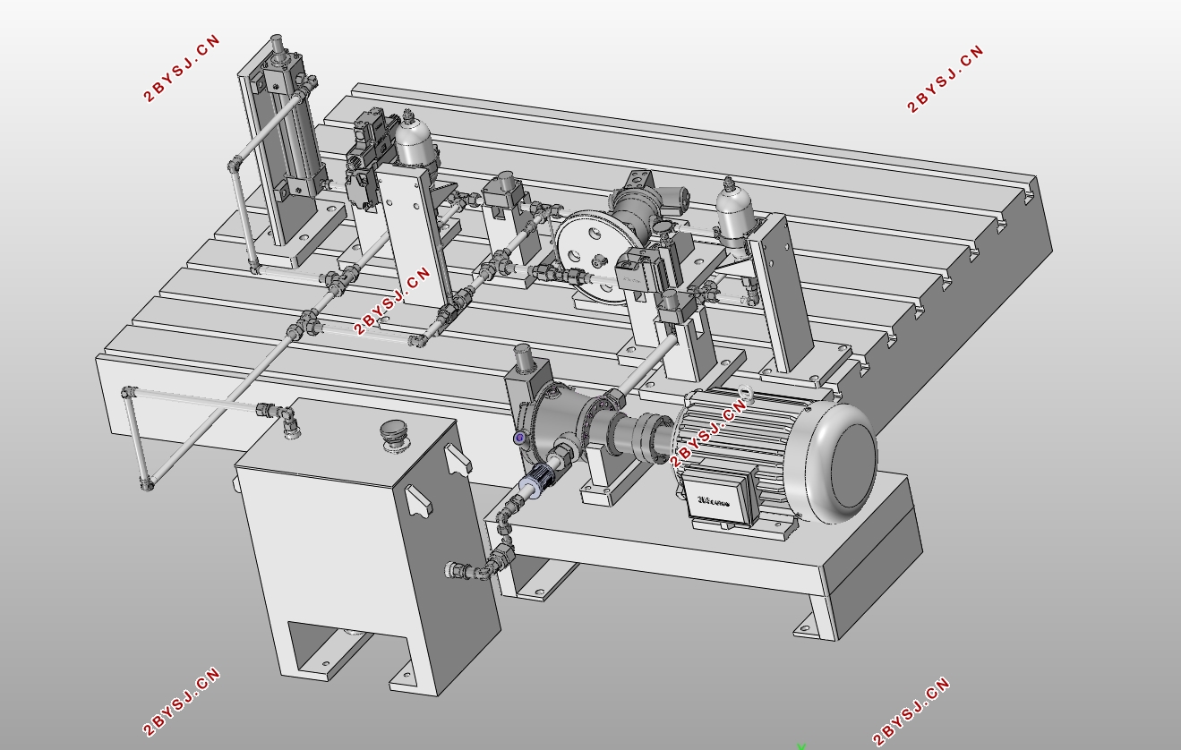
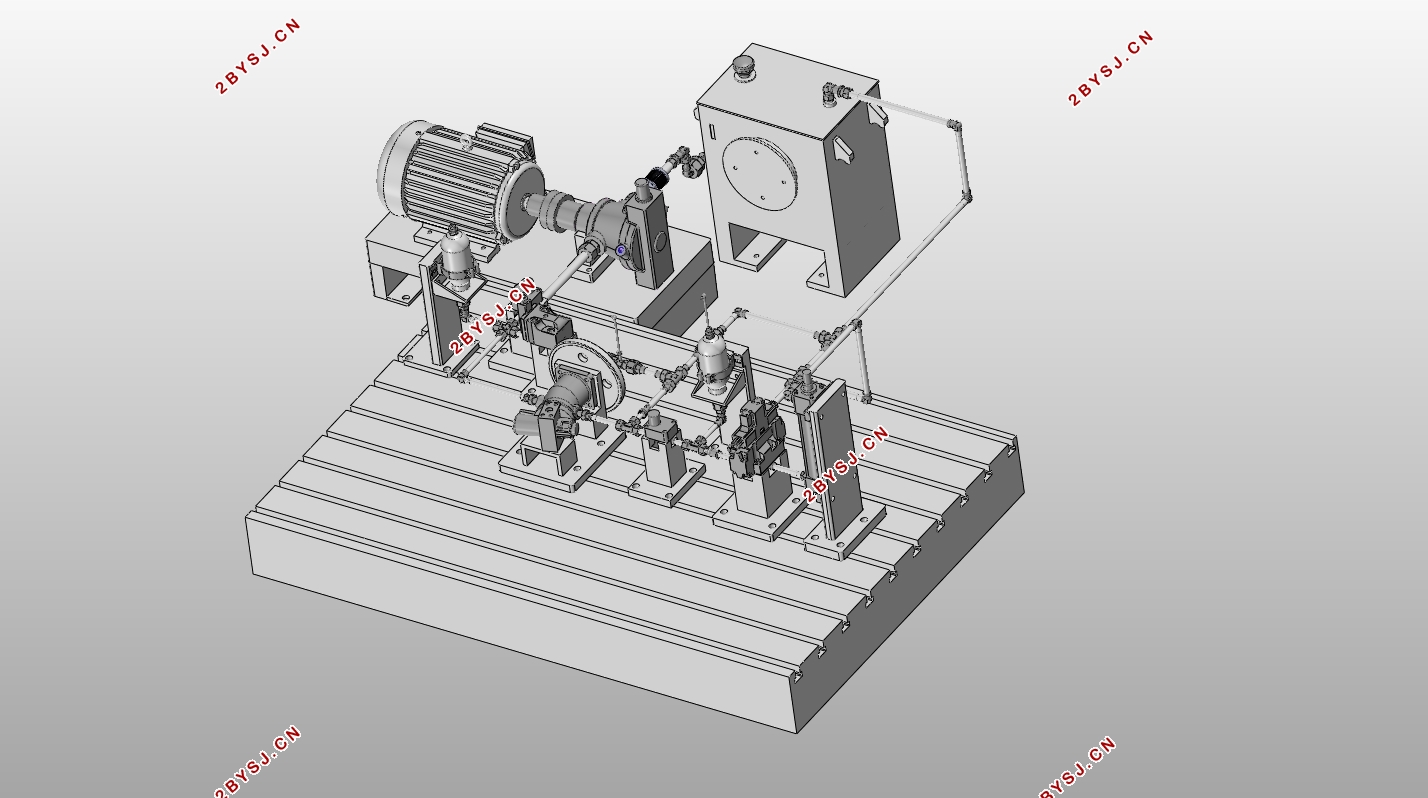
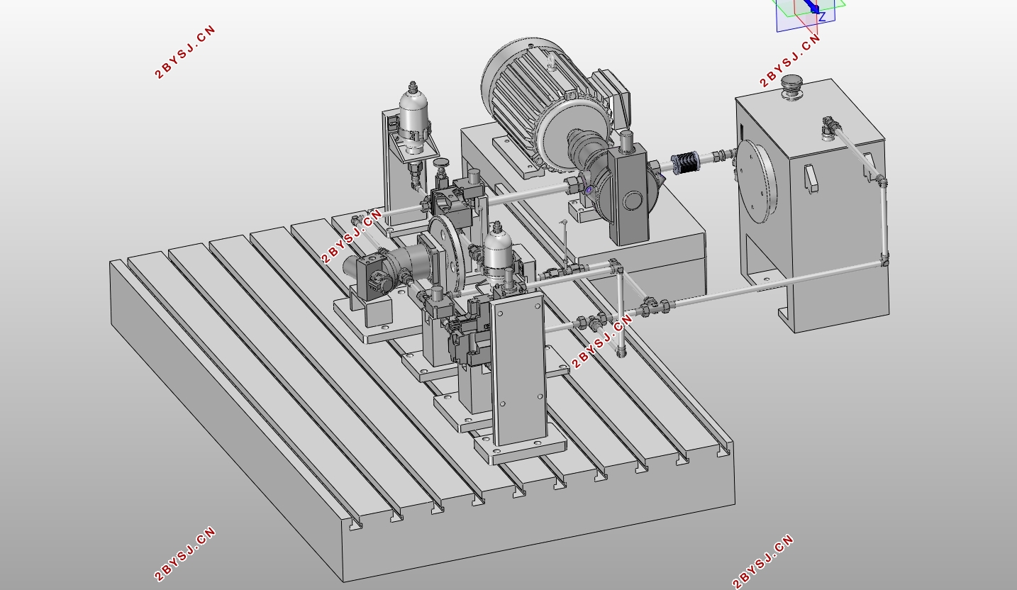
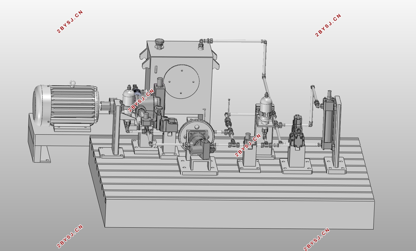

目录
第1章 绪论 1
1.1研究背景 1
1.2目的和意义 1
1.3国内外研究现状 2
1.4预期目标 2
第2章 基本原理 3
2.1液容和液感 3
2.1.1液容元件 3
2.1.2液感元件 3
2.2变压型液压源系统 3
2.2.1升压型开关电源原理 4
2.2.2升压型液压驱动系统工作过程分析 4
第3章 系统计算及元件选型 8
3.1液容 8
3.1.1输入液容 8
3.1.1.1输入液容蓄能器参数计算 8
3.1.1.2输入液容蓄能器型号选择 9
3.1.2输出液容 9
3.1.2.1输出液容蓄能器参数计算 9
3.2液感元件 9
3.2.1长管道液感 9
3.2.2液压马达带动飞轮结构液感 10
3.3高速开关阀 11
3.4其他元件 11
3.4.1高速单向阀 11
3.4.2液压缸 12
3.4.3油箱 12
3.4.4管件 13
3.4.4.1管路 13
3.4.5泵的选择 14
3.4.6电动机的选择 15
第4章 系统模拟及仿真 16
4.1液压升压系统仿真 16
4.2系统建模对比分析 19
第5章 结论与展望 22
参考文献 23
致谢 24
附录A 25
