数控复合齿轮加工实验中心的设计(含CAD图,IGS三维图)
无需注册登录,支付后按照提示操作即可获取该资料.
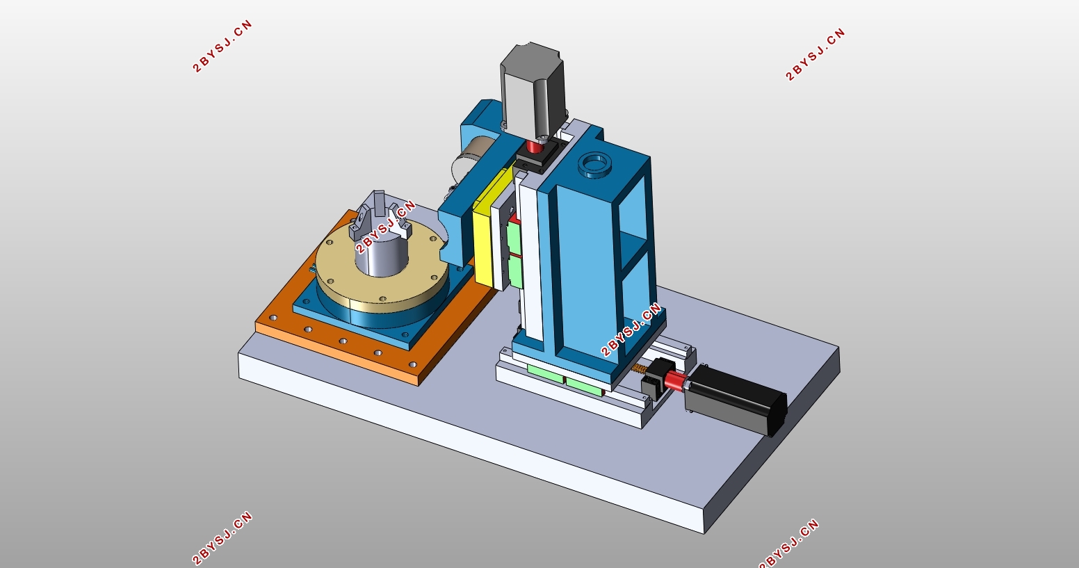
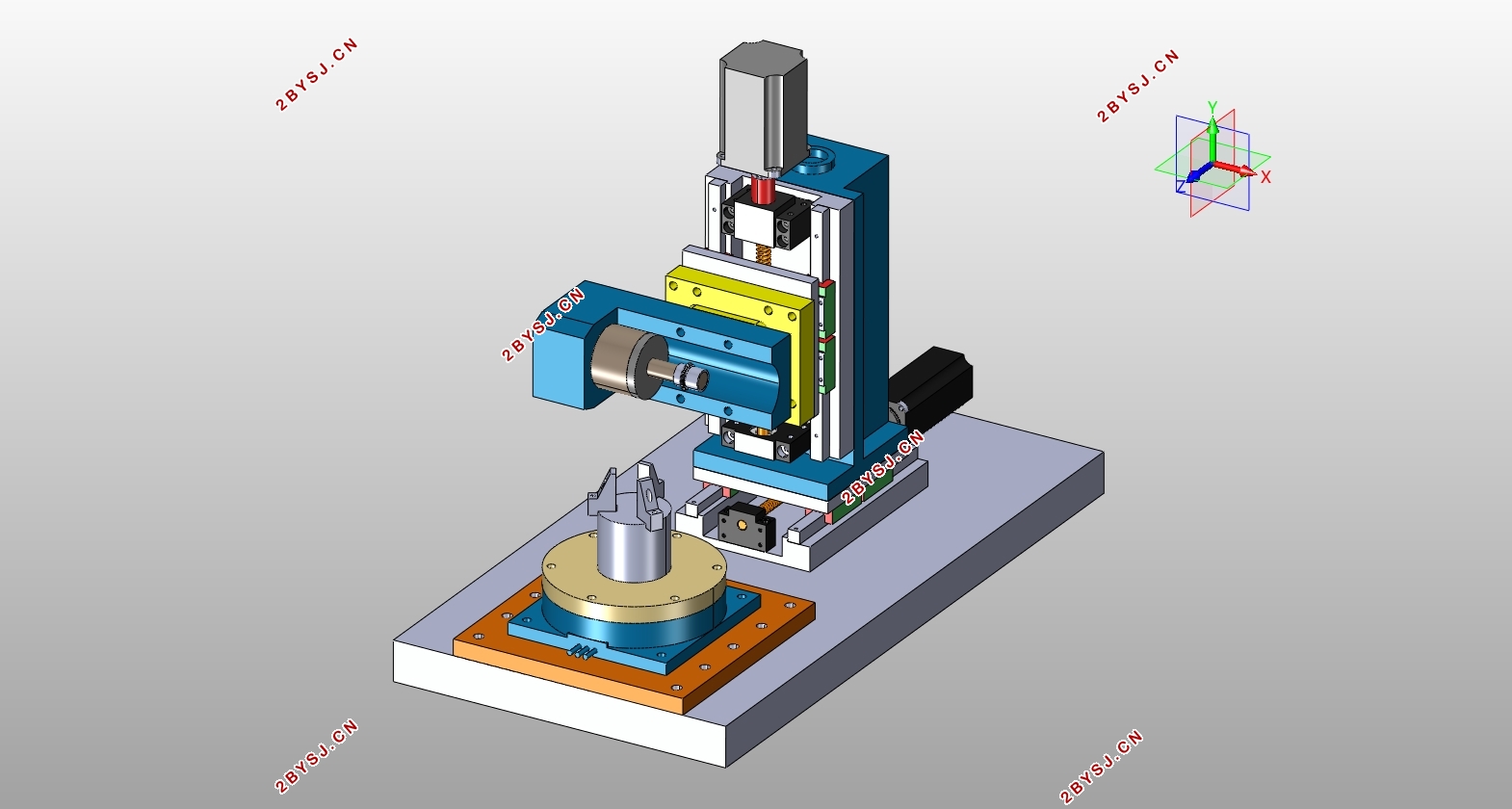
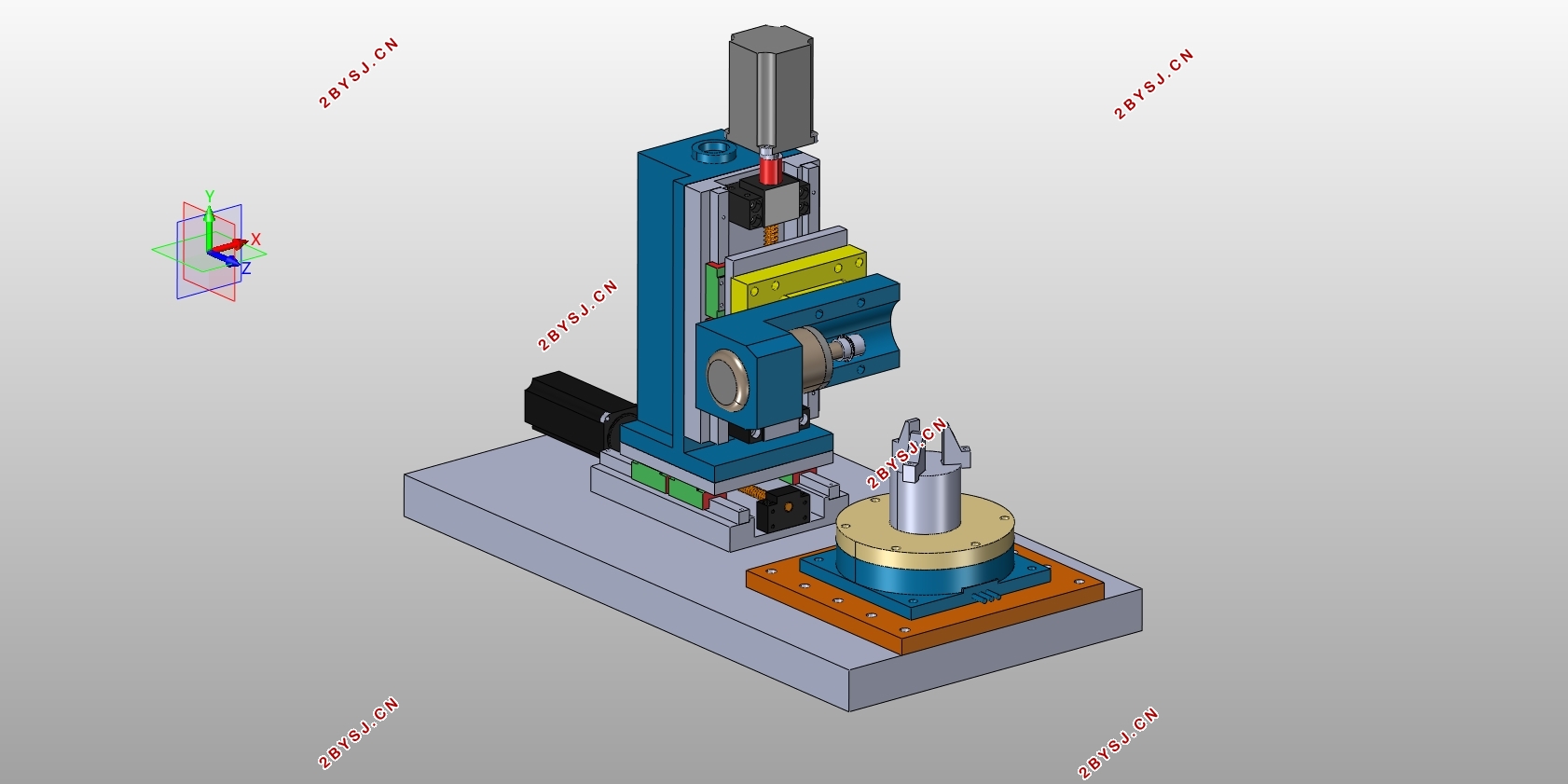
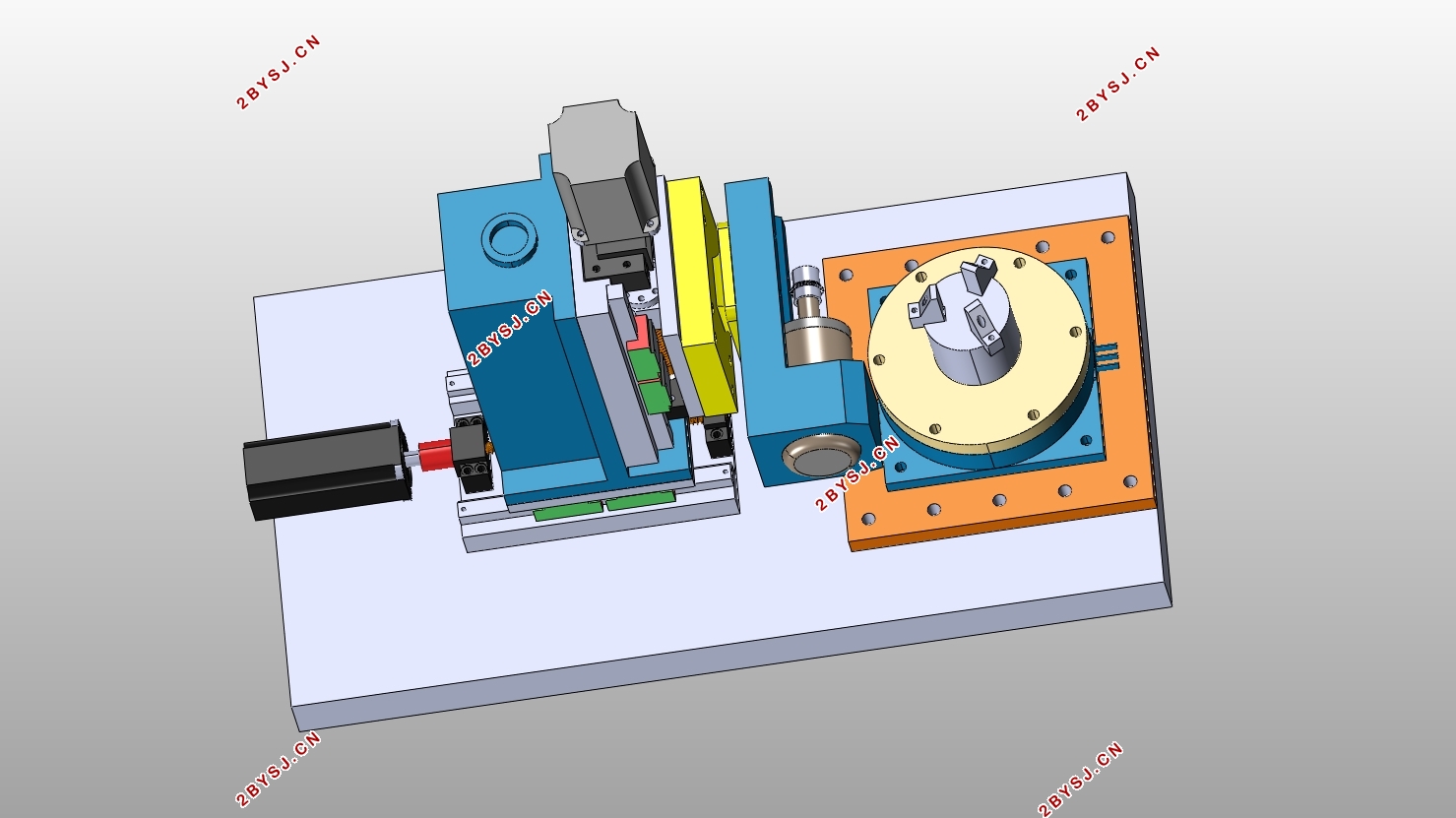
数控复合齿轮加工实验中心的设计(含CAD图,IGS三维图)(任务书,开题报告,论文说明书10000字,CAD图4张,IGS三维图,答辩PPT)
摘要
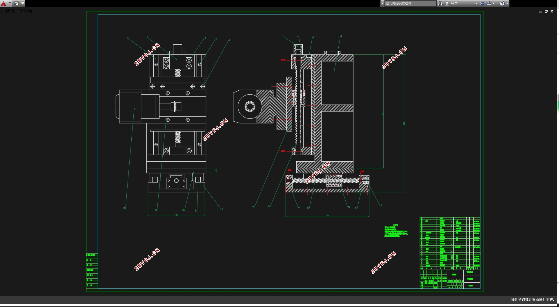
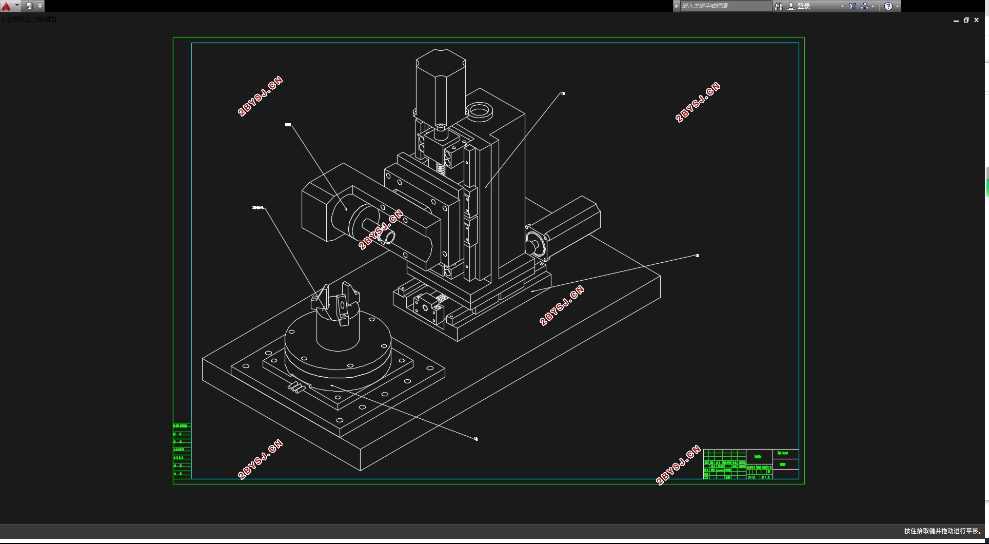
了解数控机床的基本构造并掌握铣齿机的加工步骤,并按照标准计算过程选择X(水平方向进给)轴与Z轴(垂直方向进给)所需零部件的型号尺寸,进行校核验证,使组装完成后的机床可以在西门子808D铣削数控系统的控制下完成对铝合金材质的直齿圆柱齿轮的加工,学习数控编程的基本原理,完成对直齿圆柱齿轮的基本编程,并对齿轮加工后的误差进行分析,总结经验,同时将滚齿加工与模数铣齿加工进行比较,分析其利弊,进一步了解滚齿的加工原理以及注意事项。
关键词:铣齿 选型校核 数控编程 滚齿
Abstract
Understand the basic structure of NC machine tool and master the processing steps of gear milling machine, and select the size of parts needed by X (horizontal feed) axis and Z (vertical feed) axis according to the standard calculation process, and check and verify, so that the assembled machine tool can complete the processing of straight cylindrical gear of aluminum alloy material under the control of Siemens 808D milling NC system. Learning the basic principle of NC programming, completing the basic programming of spur gear, analyzing the error after gear processing, summing up experience, and comparing Hobbing with numerical milling, analyzing its advantages and disadvantages, further understanding the hobbing processing principle and matters needing attention.
Key words: milling tooth;selection check;NC programming;gear rolling


目录
第一章 绪论 1
1.1前言 1
1.2数控机床的产生与发展历程 1
1.3数控机床的发展趋势 2
1.4本课题研究目的 3
第二章 总体设计 4
2.1设计的一般要求 4
2.2数控机床的分类 4
2.3数控机床的检测装置 5
2.4数控加工中心组成部分 7
2.5注意事项 9
第三章 计算说明及选型 10
3.1铣削力的计算 10
3.2 X轴相关计算 10
3.3 Z轴相关计算 15
第四章 数控加工程序及说明 19
4.1直齿轮的数控编程 19
4.2直齿轮误差分析 20
4.3西门子808D数控铣削系统简介 21
第五章 对滚齿机的初步了解 22
5.1滚齿加工简介 22
5.2滚刀的选择及使用 23
第六章 机床经济性 25
6.1主要零部件的采购信息 25
6.2对于成本结构的分析 25
第七章 总结 26
参考文献 27
致谢 28
