中型客车手动变速器设计(含CAD图,STEP三维图)(英文版)
无需注册登录,支付后按照提示操作即可获取该资料.
中型客车手动变速器设计(含CAD图,STEP三维图)(英文版)(任务书,开题报告英文版,外文翻译,文献摘要,论文说明书英文版10300字,CAD图6张,STEP三维图)
摘 要
变速器是用来改变发动机传递到驱动轮上的转矩和转速,目的是在原地起步,爬坡,转弯,加速等各种行驶工况下,使汽车获得不同的牵引力和速度,同时使发动机在最有利工况范围内工作。变速器设有空挡和倒挡。需要时变速器还有动力输出功能。
本设计变速器为机械式手动变速器,五个前进档均装有锁环式惯性同步器,除倒档外,传动齿轮均采用斜齿轮,从而使变速器寿命延长,噪声降低,使换档轻便、灵活。机械式变速器因具有结构简单,传动效率高,制造成本低和工作可靠等优点,在不同形式的汽车上得到广泛应用。
本次设计内容包括:1、变速器传动机构布置方案,2、变速器主要参数的选择,3、变速器齿轮的设计与计算 ,4、变速器轴的设计与计算,5、同步器设计,6、变速器操纵机构,7、变速器结构元件七部分。
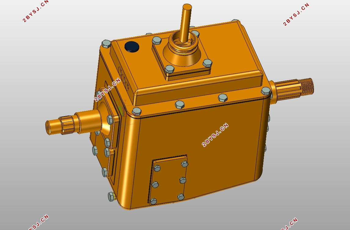
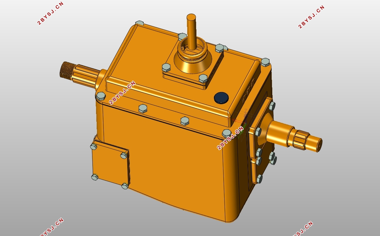
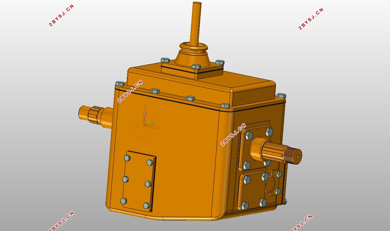
本次设计在参数、数据已计算的前提下,综合应用UG零部件功能和装配功能,对变速器进行了绘制和装配的三维设计。同时利用CAD绘制平面图。
Abstract
The transmission is used to change the torque and speed that the engine transmits to the drive wheels. The purpose is to make the car get different traction and speed under various driving conditions such as starting, climbing, turning and accelerating, and at the same time, work within the most favorable conditions. Transmission has neutral and reverse gear. The transmission also has a power output function when required.
The designed transmission is a mechanical manual transmission. The five forward gears are equipped with a lock-ring type inertia synchronizer. In addition to the reverse gear, the transmission gears are helical gears, so that the transmission life is extended, the noise is reduced, and the shifting is light and flexible. Due to its simple structure, high transmission efficiency, low manufacturing cost, and reliable operation, mechanical transmissions are widely used in different types of automobiles.
The design includes: 1. Transmission transmission arrangement plan; 2. Selection of main transmission parameters; 3. Design and calculation of transmission gear; 4. Design and calculation of transmission shaft; 5. Synchronizer design; 6. Transmission operation Mechanism; 7. transmission structural elements seven parts.
In this design, under the premise of parameters and data have been calculated, the three-dimensional design of the transmission has been mapped and assembled using the functions and assembly functions of UG. At the same time using CAD to draw floorplans.
Key words:transmission; shift gear; lock-ring synchronizer; operating mechanism



Content
Chapter 1 Introduction 1
Chapter 2 Proposal 2
2.1 Transmission type selection 2
2.2 Type and layout plan of reverse gear 3
2.3 Gear shift structure and gear arrangement 4
2.3.1 Gear shift structure 4
2.3.2 Arrangement of gears 4
Chapter 3 Gears Design Calculation 6
3.1 Determination of gear parameters 6
3.1.1 Transmission ratio selection 6
3.1.2 Center distance A 7
3.1.3 The axial dimension of the transmission 8
3.1.4 Gear parameters 8
3.1.5 Determine the number of teeth 10
3.2 Gear strength calculation and material selection 19
3.2.1 Damaged form of gear 19
3.2.2 Gear strength calculation 19
3.2.3 Gear material selection 24
Chapter 4 Shaft Design Calculations 25
4.1 Shaft function and design requirements 25
4.2 Preliminary select shaft diameter 25
4.3 Structure of the shaft 28
4.4 Analysis of the force of the shaft 29
4.4.1 Force analysis of gears: 29
4.4.2 Direction 30
4.4.3 The role of each force 31
4.5 Shaft strength calculation and check 31
4.6 Shaft stiffness check 36
Chapter 5 Selection of Transmission Bearings 38
5.1 Several bearing features 38
5.1.1 Tapered Roller Bearings 38
5.1.2 Deep groove ball bearings 38
5.1.3 Angular contact ball bearings 38
5.1.4 Needle bearing 38
5.2 Bearing type selection 38
5.2.1 Bearing load 39
5.2.2 Bearing speed 39
5.2.3 Bearing alignment performance 40
5.2.4 Bearing installation and disassembly 40
Chapter 6 Synchronizer Design 42
6.1 Inertial synchronizer 42
6.2 Locking ring synchronizer works 42
6.3 Determination of main parameters 43
Chapter 7 Keys’ selection and operating mechanism 46
7.1 Key connection type 46
7.2 Keys selection 46
7.3 Spline on shaft selection 46
7.4 Operating mechanism 47
Summary 49
References 50
致谢 51
