筒形件锥形压边圈拉深模具的动画制作(Proe三维图,仿真视频)
无需注册登录,支付后按照提示操作即可获取该资料.
筒形件锥形压边圈拉深模具的动画制作(Proe三维图,仿真视频)(任务书,中期检查表,论文说明书18400字,Proe三维图,仿真视频动画)
摘 要
本设计题目为筒行件锥形压边圈拉深模具的动画制作,体现了运用三维建模软件Pro/ENGINEER Wildfire对拉深模具的设计、制作、装配和动画演示过程,极有一定的意义,通过对该零件模具的设计,进一步加强了设计者拉深模设计的基础知识,为设计和演示更复杂的拉深模具的动作过程做好了铺垫和吸取了更深刻的经验。
本设计运用冲压工艺与模具设计的基础知识,首先进行了拉深模的工艺分析,为动画部分各零件先后运动的次序奠定了基础,然后运用Pro/ENGINEER Wildfire对拉深模各零件经行了实体生成,为装配做好了准备,最后介绍了动画的制作过程,使学习者对拉深模具的动作过程有了更进一步的理解。
本设计主要运用了三维建模软件Pro/ENGINEER Wildfire,在设计过程中不仅巩固了拉深模具的基础知识,更进一步的学习和掌握了运用Pro/E进行动画设计的方法和步骤,使软件和书本结合起来,两者相互映衬,意义重大。
关键词:拉深模 装配 动画
The animation of the drawing die with tube and conical of blankholder
Abstract
The design of production, assembly and demonstration of the process of animation of drawing die are embodied on this injection mould design of the cylinder subject line blank holder cone pieces drawing die animation with Three-dimensional modeling software Pro / ENGINEER Wildfire through the design of the die, The designer’s foundation knowledge of drawing die design is reinforced and is able to design and demonstration of more complex movements drawing mould through the design.
Through the foundation knowledge, firstly, the technology of drawing die is analyzed to movement the order of the animation part of the various parts, Secondly,with the line of entities generated,it is readyed to assembly for the parts of drawing die through the line of entities generated by use of Pro / ENGINEER Wildfire. Lastly the character of the part is introduced about the production process of animation,though it, the students would have further understanding of the process of drawing die movements.
This design not only study the design process but also consolidate the basic knowledge by use of the design of three-dimensional modeling software Pro / ENGINEER Wildfire,t the background of the two each other against have a great significance.
Keywords: Drawing Die Assembly Animation
目 录
第1章 拉深模具零件的制造 1
1.1拉深工艺的简介和分析 1
1.2 PRO/ENGINEER简介 2
1.2.1 Pro/ENGINEER的特点 3
1.2.2 Pro/ENGINEER的模块与功能 4
1.3 PRO/ANIMATION的简介 8
1.4实体生成 8
1.4.1下模座的制作 8
1.4.2 凸模固定板的制作 12
1.4.3 凸模的制作 13
1.4.4 压边圈的制作 14
1.4.5 凹模的制作 18
1.4.6 上模座的制作 20
1.4.7 打杆的制作 24
1.4.8 挡料销的制作 27
1.4.9 垫板的制作 29
1.4.10 上模座螺钉的制作 30
1.4.11 上模座螺母的制作 33
1.4.12 推件块的制作 35
1.4.13 下模连接杆的制作 36
1.4.14 推杆的制作 38
1.4.15 下模座垫板的制作 39
1.4.16 橡皮的制作 40
第2章 拉深模的装配 42
2.1 装配设计的基本方法简介 42
2.2 装配设计的基本步骤 42
2.3下模部分的装配 43
2.4 上模部分的装配 60
第3章 拉深模动画的制作 63
3.1概述 63
3.2动画创建的一般流程 63
3.3 解除约束 64
3.4 主体定义 65
3.5拖动和快照 65
3.6 条料的送进 66
3.7 压料过程的制作 66
3.8 制品脱出过程 67
结论 68
致谢 70
参考文献 71
插图清单
图1-1 绘制草图 9
图1-2 定义平面 9
图1-3 选择切口 10
图1-4 绘制扫描轨迹 10
图1-5 绘制扫引截面 10
图1-6 草绘平面 11
图1-7 下模座实体 12
图1-8 草绘平面 13
图1-9 凸模固定板实体 13
图1-10 草绘轨迹 14
图1-11 草绘轨迹 15
图1-12 草绘轨迹 15
图1-13 草绘轨迹 16
图1-14 草绘轨迹 16
图1-15 选择切口并绘制扫引轨迹 17
图1-16 绘制截面 17
图1-17 绘制草图轨迹 18
图1-18 绘制旋转草绘 19
图1-19 绘制拉深草绘平面 19
图1-20 旋转体草绘平面 20
图1-21 凹模实体 20
图1-22 绘制上模座拉深草图 21
图1-23 绘制草图 22
图1-24 绘制草图 22
图1-25 绘制草图 22
图1-26 绘制草图 23
图1-27 绘制草图 23
图1-28 绘制草图 23
图1-29 上模座螺钉孔草图 24
图1-30 绘制拉深草图 25
图1-31 绘制扫引轨迹 25
图1-32 绘制截面 26
图1-33 绘制拉深草图 26
图1-34 绘制扫引轨迹 26
图1-35 绘制截面 26
图1-36 绘制草图 27
图1-37绘制拉深草图 28
图1-38 绘制草图 28
图1-39 绘制扫引轨迹 28
图1-40 绘制截面 29
图1-41 绘制垫板轮廓草图 30
图1-42 绘制通孔草图 30
图1-43 绘制上模座螺钉肩部草图 31
图1-44 绘制旋转草图 31
图1-45 绘制螺杆草图 32
图1-46 绘制扫引轨迹 32
图1-47 截面草图 33
图1-48 绘制螺母轮廓草图 33
图1-49 通孔草图 33
图1-50 旋转草图 34
图1-51 扫引轨迹 34
图1-52 截面 35
图1-53 推件块轮廓 35
图1-54 扫引轨迹 36
图1-55 截面草图 36
图1-56 连接杆拉深草图 37
图1-57 扫引轨迹 38
图1-58 截面 38
图1-59 推杆拉深草图 39
图1-60 扫引轨迹 39
图1-61 截面 39
图1-62 下模座垫板轮廓草图 40
图1-63 通孔草图 40
图1-64 橡皮轮廓草图 41
图2-1 拉深模具装配实例结构 42
图2-2 在打开的对话框选择要装配的零件 43
图2-3 选择约束类型 44
图2-4 指定轴 44
图2-5 选取轴 45
图2-6 指定匹配的面 45
图2-7 凸模和凸模固定板装配图 46
图2-8 凸模的装配关系 47
图2-9 下模座螺钉的约束关系 48
图2-10 螺钉装配关系 49
图2-11 装配好的螺钉模型 49
图2-12 销钉的装配约束关系 50
图2-13 装配好的销钉模型 50
图2-14 装配压边圈的约束关系 52
图2-15 装配推杆的约束关系 53
图2-16 选取阵列中心轴 54
图2-17 确定连接杆的装配约束关系 55
图2-18 确定推杆的约束关系 56
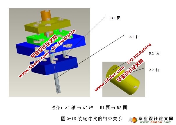
图2-19 装配橡皮的约束关系 57
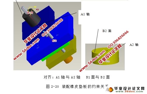
图2-20 装配橡皮垫板的约束关系 58
图2-21 确定垫片的约束关系 59
图2-22 在打开的对话框选择要装配的零件 60
图2-23 在状态栏下显示“完全约束” 61
图2-24 装配上模座约束关系 62
图3-1 进入动画界面 64
图3-2 取消约束 65
图3-3 进入“关键帧序列” 66
图3-4 选取“Z”轴 66
