基于单片机的温控智能红外遥控风扇设计
无需注册登录,支付后按照提示操作即可获取该资料.
基于单片机的温控智能红外遥控风扇设计(任务书,开题报告,外文翻译,论文11000字)
摘要
随着科技的发展,人们生活质量的不断提高,家电逐渐趋于智能人性化。这就使得单片机控制的家电得以发展。
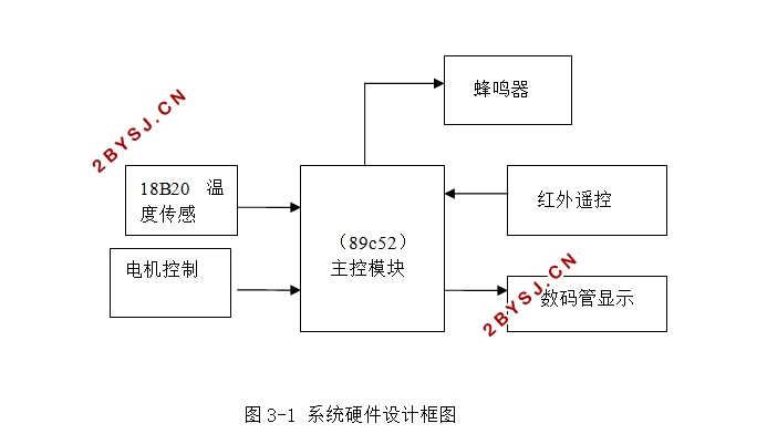
本设计为一种温控风扇系统,具有灵敏的温度感测和显示功能,系统STC89C52单片机作为控制平台对风扇转速进行控制。可由用户设置高、低温度值,测得温度值在高低温度之间时打开风扇弱风档,当温度升高超过所设定的温度时自动切换到大风档,当温度小于所设定的温度时自动关闭风扇,控制状态随外界温度而定。所设高低温值保存在温度传感器DS18B20内部E2ROM中,掉电后仍然能保存上次设定值,性能稳定,控制准确。
关键词:智能风扇;红外遥控;蜂鸣报警
Intelligent infrared remote control fan with temperature
control based on MCU
Abstract
With the development of science and technology, people constantly improve the quality of life, and home appliances gradually become intelligent This makes home appliances controlled by MCU to develop.
This design is a temperature controlled fan system, with a sensitive temperature sensing and display function.High, low temperature can be set by user When the measured temperature value is between the high and low temperature, people can turn on the weak wind grade When the temperature rises up to the set temperature, the fan automatically switches to the strong wind grade. When the temperature is less than the set temperature, the fan automatically turns off. Control state changes according to the outside temperature. The high and low temperature are stored in the temperature sensor DS18B20 E2ROM. After power down, the fan can still save the last time setting, which has stable performance and can be accurately controlled.
Key word: Intelligent fan; infrared remote control; beep alarm


目录
摘要 I
Abstract II
第一章 绪论 1
第二章 设计要求和方案论证 3
2.1 设计要求 3
2.2 系统设计方案及论证 3
2.2.1 控制核心 3
2.2.2 温度采集模块 4
2.2.3 显示电路模块 5
2.2.4 电机调速方式 5
2.2.5 智能启动模块 5
第三章 智能风扇硬件电路的设计 7
3.1 电路硬件概述 7
3.2 主控模块 7
3.3 温度采集模块 9
3.4 红外遥控模块 10
3.5 电机调速电路 11
3.5.1 电机调速原理 12
3.5.2 电机控制模块设计 13
3.6 整体电路 14
第四章 软件设计 16
4.1 主程序 16
4.2 数字温度传感器模块 17
4.3 电机调速模块 18
第五章 系统调试 20
5.1 硬件调试方法 20
5.2 程序调试 20
第六章 总结与展望 22
6.1 总结 22
6.2 展望 22
致谢 23
参考文献 24
附录一 系统电路图 25
附录二 程序 26
