
�羶99m�³�ʽ�ֹܻ�����ϵ�˹������(��CADͼ)
����ע���¼,֧��������ʾ�������ɻ�ȡ������.
�羶99m�³�ʽ�ֹܻ�����ϵ�˹������(��CADͼ)(������,���ⱨ��,���˵����20000��,CADͼֽ26��)
ժҪ
�ֹܻ�������һ����ѹ������ǿ�IJ��ϣ��������Գ�ѹΪ���Ĺ����еõ��㷺��Ӧ�á��ֹܻ��������Ž�֮��ͳ���ع�������ֽ���������ţ��������ǿ�ȵ������ʩ���ķ��㣬ʹ����к�ǿ�ı�������
������ҵ�����ĿΪ�³�ʽ�ֹ������ͻ�����ϵ�˹��ţ����Ŀ羶��99m�����ȸ�����ƾ��鼰����Ҫ���ⶨ����������Ҫ��������ϸ���ߴ磻���ǵ����������ĵ��ε�ò������������4.316m�ߵ���ʽ�գ����ݵ������ѡ��Ħ����Ϊ���������ȷ��ʩ��������������֧���ֽ�ʩ����
֮������MIDAS/CIVIL�������нṹ����Ԫ�����������ⶨ�����ߴ罨����������ģ�ͣ���������������ԤӦ����Ĺ����벼���Լ��������㡣��ģʱ�����˻�����������䡢�¶ȡ������ص�Ӱ�죬Ȼ����к�����ϣ������ݺ�����Ͻ��.��������ش������ķ�����ͬʱ���������г����塢ê�¾ֲ���ѹ���Ŷռ�������������㡣���Ըֽ�������ṹ���ֽ����������ǿ�����㡣��������塢���˵ȹ����������㣬����Ӧ����ǿ��Ҫ��
�������������������Ƽ��㷽����ȷ�������ֲ������������������Ҫ��
�ؼ��ʣ��³�ʽ�ֹܻ�����ϵ�˹��ţ��ṹ������MIDAS/CIVIL
Abstract
Concrete-filled steel tube is a kind of material with strong compression ability.Compared with traditional masonry arch bridge and reinforced concrete arch bridge, concrete-filled steel tubular arch bridge has a strong expressive force due to the improvement of material strength and the convenience of construction.
This graduation design topic is the steel pipe dumbbell type concrete arch bridge, its span is 99m. Based on the design experience and construction requirements, the main structure and the relevant details of the main girder are proposed. In consideration of the topography of the bridge, the pier adopts a column pier with a height of 4.316m. The friction pile is selected as the foundation according to geological conditions. Secondly, the construction method is determined, and the construction of less stents is adopted.
After that, the MIDAS/CIVIL software was used for finite element analysis. According to the proposed bridge size, the basic model of the bridge is established, and the calculation and layout of the internal force analysis and the prestressing tendon are carried out. The influence of concrete shrinkage and creep, temperature and other factors was considered in modeling, then the load combination was carried out, and the analysis of relevant secondary forces was carried out according to the result of load combination. At the same time, the related hand calculation is carried out on the road plate, the local pressure under the anchor, the bridge pier and the foundation. In addition, the reinforcement calculation and strength checking of reinforced concrete structure are carried out. Finally, the bridge panel, hanger rod and other components are checked to meet the requirements of stress and strength.
The analysis results show that the design calculation method is correct, the internal force distribution is reasonable, and the design task is completed.
1.3 ��ƻ�������
1.3.1 �������
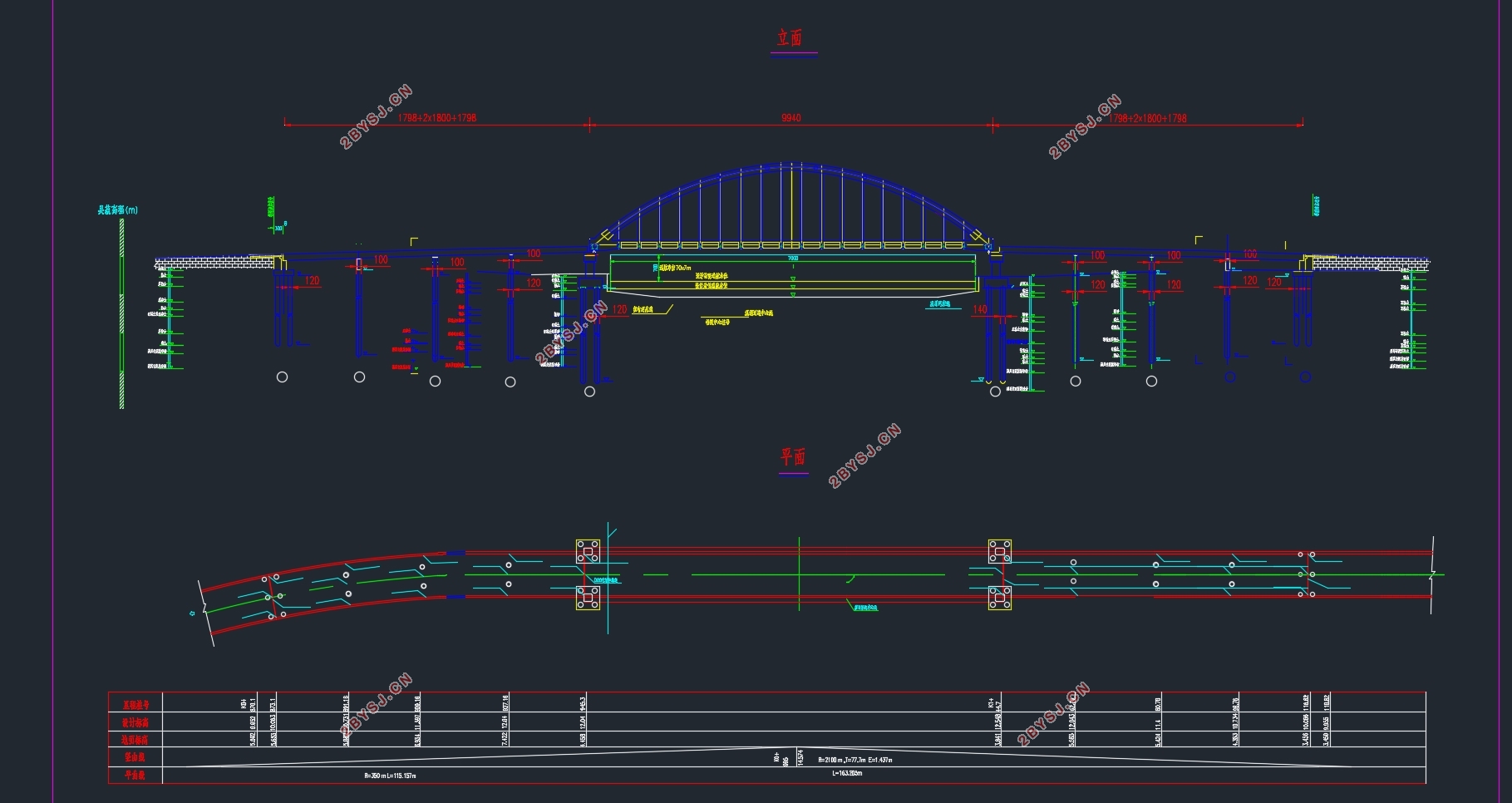
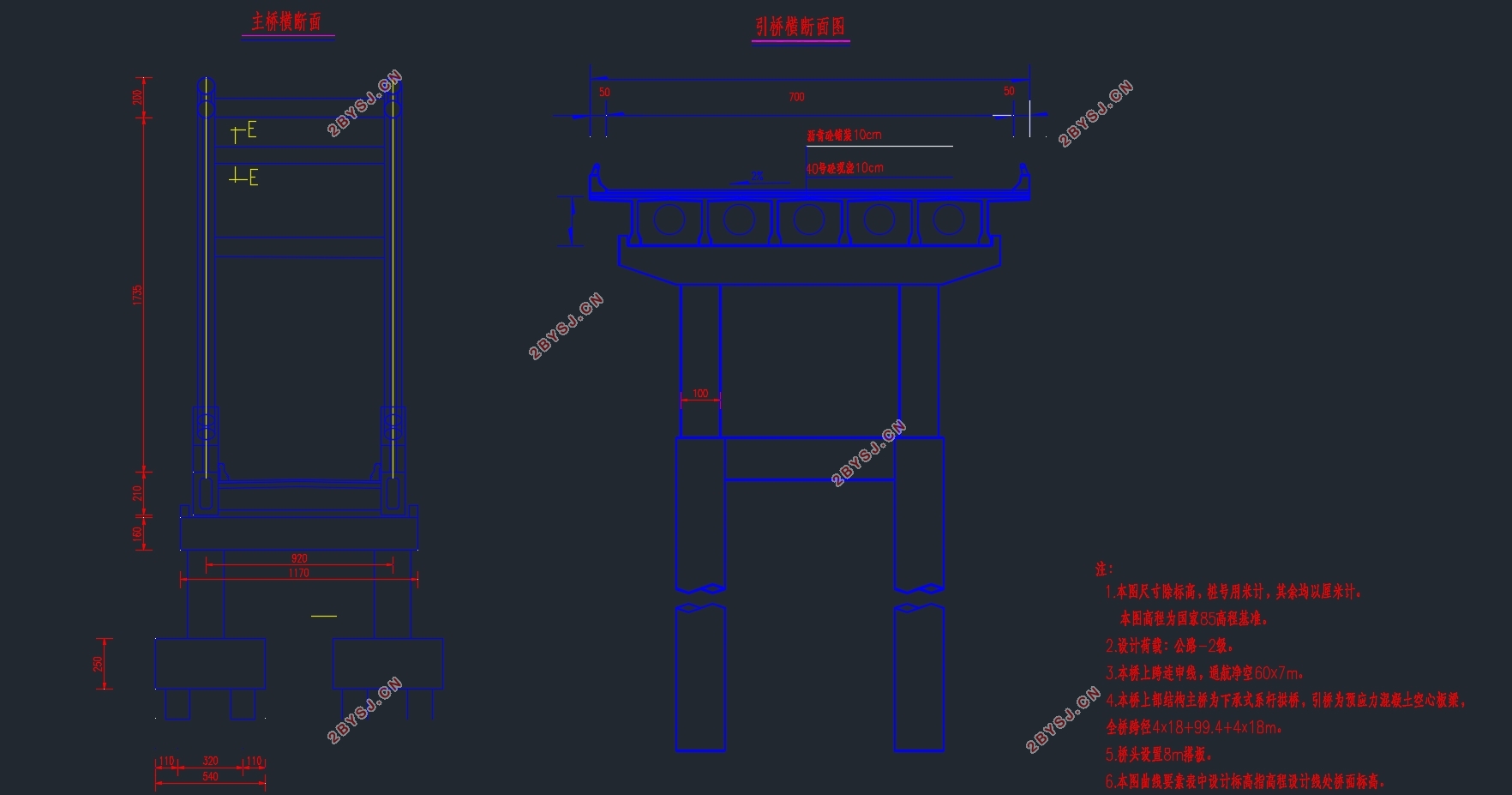
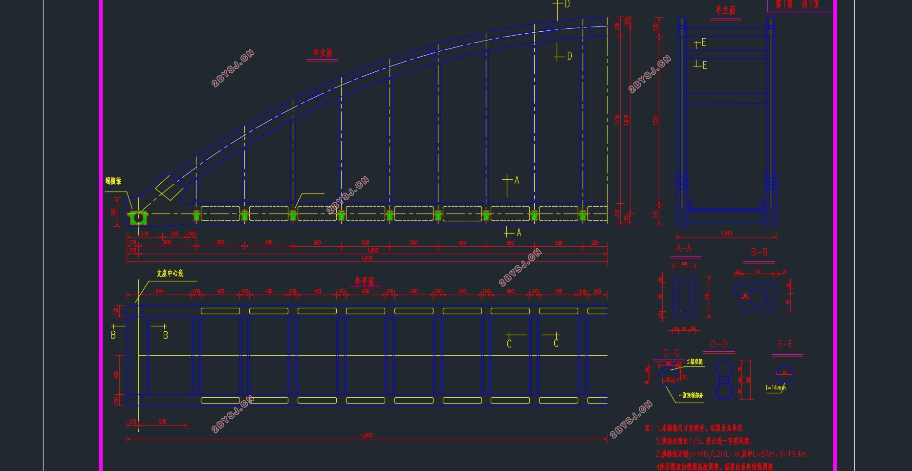
��������99m��ϵ��Ϊ��֧���ֽ�ʩ���������ֶβ��õ�װƴװ���ӡ���ƺ���Ϊ��·2������������q =7.8kN��P =270kN����Ƴ���Ϊ30km/h�������������Ϊ���࣬�ź��ṹ��ƻ���Ϊ100�ꡣ
����Ϊ99m�³�ʽ�ֹܻ�����ϵ�˹��ţ��������������4*18����װ��ʽԤӦ�����������������ȫ���ܳ�244m�����������ĵ������죬����IJ���Ϊ����������
�²���ѡ���߰�̨����ʽ�պ����ע���������������Ҫ���õ�����Ϊmidas���������ϲ��ṹ������ƣ�ͨ����MADAS�����н�������Ԫģ�ͣ��Ӷ������������������з������㡣��ʹ��Madis/civil����֮ǰ�������ȫ�Žṹ������ɢ�������ֵ�Ԫ�ڵ㣬����Ԫ�DZ�ʾʵ����������ɢ��Ԫ�ļ��ϣ��ṹͨ����ͬ�Ľڵ����ӳɲ�ͬ�ĵ�Ԫ�������Ӷ��������ز�������ƣ���Ԫ���õ�����Ҳ��һ������Ҫ�Ĺ��̣������Ԫ���ù��࣬�������Ӻܶ�����������Ԫ���ù��٣�ģ����Ƶľ���Ҳ����֮���͡���ˣ�����Ҫ��һ���Ⱥ;��ȵĻ����ϣ���MADAS��Ԫ���к���������ѡ����ҲҪ��ʩ��������������
1.3.2 ��Ҫ����ָ��
�ڱ�����в��õ���Ҫ���������£�
��ƺ��أ���·2����
��������С�뾶����������Ϊ5000m
�����1.0m
������²30�bC������²30�bC

Ŀ ¼
Abstract III
��1�� ����������ϸſ� 1
1.1 ��Ƴ�ʼ���� 1
1.2 ������Ʒ����Ƚ� 1
1.2.1�������ͷ�����ѡ 1
1.3 ��ƻ������� 4
1.3.1 ������� 4
1.3.2 ��Ҫ����ָ�� 5
1.3.4��Ҫ���� 5
1.4 �����ṹ�ߴ��ⶨ����� 6
1.4.1 �����ϲ��ṹ�ⶨ 6
1.4.2 ���߸ֹܻ������ṹ�ⶨ 6
1.4.3 ԤӦ���Ӿ����ṹ�ⶨ 7
1.5 ����ʩ������ 7
1.6 MIDAS/CIVIL����ģ����ϸ���� 10
��2�� ������������ 14
2.1 ������������ 14
2.1.1 �����ſ� 14
2.1.2 ���粿�ֽ��漸�����ʼ����� 14
2.1.3 ���� 16
2.1.4 MIDAS/CIVILģ�͵�Ԫ�������� 17
2.1.5 ���������� 17
2.2������� 21
2.1.1 �������ԭ�� 21
2.1.2 ������Ͻ�� 24
��3�� �ֹܻ���������ǿ������ 29
3.1 ����ǿ������ 29
��4�� ����ǿ������ 33
4.1 ����ǿ������ 33
4.1.1 ���� 33
4.1.2 ������������ 33
4.1.3 �������� 35
4.2.2ϵ����������ͼ 41
4.2.3ϵ������ 42
4.2 ����ԤӦ����������ʧ���� 46
4.2.1 ������� 46
4.2.2 �������������� 47
4.2.3 ԤӦ����������Ĺ��㼰�����IJ��� 49
4.2.4 �������漸�����Լ��� 53
4.2.5 ����ԤӦ����ʧ���� 53
4.2.6 ʩ���ε�������Ӧ������ 57
4.2.7 ʹ�ýε���Ӧ������ 58
4.2.8����ǿ�ȼ��� 61
4.2.9 �������Σ��Ӷȣ����� 66
��5�� �²��ṹ��� 74
5.1 �²��ṹ�ߴ��ⶨ 74
5.1.2 �����ߴ��ⶨ 74
5.1.3 ��̨�ߴ��ⶨ 76
5.2 ���ע���� 77
5.2.2 �����ⶨ 77
5.2.3 ��������ƽ�沼�� 77
5.24������������ 78
��6�� ������ά����Ԫģ�� 82
6.1��������ģ�� 82
6.2ģ�ͽ���������� 82
��л 90
����� 91