跨径为3×30m共90m杨泗港大桥N8联连续箱梁桥结构设计(含CAD图)
无需注册登录,支付后按照提示操作即可获取该资料.
跨径为3×30m共90m杨泗港大桥N8联连续箱梁桥结构设计(含CAD图)(任务书,开题报告,论文说明书23000字,CAD图纸20张)
摘要
杨泗港大桥是武汉市长江上的第十座长江大桥,它是一座双层12车道桥,主跨1700m,是世界上跨度第二的悬索桥。本次毕业设计选取杨泗港大桥的N8联连续箱梁桥作为设计对象。连续梁桥是工程上广泛使用的一种桥型,这种桥型集强度可靠,行车舒适平稳等优点的同时在后期养护及抗裂方面也表现出优于其它桥型的特点。一座桥梁的设计不仅是桥跨布设,截面尺寸拟定,预应力布设,施工方法的选择等方面的综合设计考虑,设计参数及环境影响在桥梁设计中也是不可忽略的。
N8联连续梁桥作为杨泗港大桥的引桥的一段,其跨径为3×30m,共90m。采用预应力连续箱梁结构设计,桥面宽17.5m,梁高为2m。桥面横向布置为:0.5m防撞墙+7.5m机动车道+1.5m隔离带+7.5m机动车道+0.5m防撞墙。荷载等级为公路-Ⅰ级荷载,箱梁横断面设计为单箱双室截面。本桥的施工采用满堂支架现浇施工方法,并用midas软件对桥梁上部结构进行建模和计算,省去了超静定结构体系内力计算的复杂。对于下部结构,本设计的主要设计内容包括盖梁、墩柱、桩基等的设计和计算。
关键词:连续梁;预应力;midas建模;箱梁
Abstract
Comprehensive consideration of the draft must be mature N8 span in the Yang Si Gang Bridge in Wuhan City, the Yangtze River on the ten blocks Yangtze River Bridge, it is a two storeyed 12 bridge, with a main span of 1700m, is the world's second suspension bridge. The graduation design selected Yang Si Gang Bridge continuous box girder bridge as a design object. Continuous girder bridge is widely used as a bridge, it not only has reliable strength, stiffness and crack resistance, and with driving smooth and comfortable, maintenance workload is small, the design and construction experience. Design a bridge from the bridge span layout, the size, the steel beam layout and construction methods, but also give full consideration to the design parameters and environmental impact .
N8 combined continuous girder bridge as Yang Si Gang bridge approach of a, the span is 3 x 30m. The prestressed continuous box girder structure design, wide bridge 17.5m, transverse beam height 2m deck layout: 0.5m collision wall +7.5m motorized vehicles +1.5m isolation +7.5m motorized vehicles +0.5m bump wall. Load level for highway - grade I load, box girder cross section design for single double room section. The construction of the bridge by framing cast-in-situ construction method, and using Midas software of bridge upper structure of modeling and calculation, eliminating the need for super statically determinate structure internal force calculation of complex. The lower part of the node The structure design and calculation including the design and calculation of beam, pier column and pile foundation design and calculation of design and calculation.
Key words: continuous beam; prestress; Midas modeling; box girder
2.1设计标准
(1) 设计荷载:机动车道为公路-Ⅰ级;
(2) 桥面宽度:0.5m防撞墙+7.5m机动车道+1.5m隔离带+7.5m机动车道+0.5m防撞墙;
(3) 桥梁结构:3×30m连续箱梁。
2.2设计资料
(1) 上部结构:C50预应力混凝土连续箱梁;
(2) 墩柱:墩柱为C30现浇钢筋混凝土;
(3) 水文地质:地下水及地表水对混凝土结构、钢筋混凝土结构中钢筋无腐蚀性;
(4) 其它:地震按动峰值加速度0.05g进行设防,其它自己拟定。
桥梁线形布置
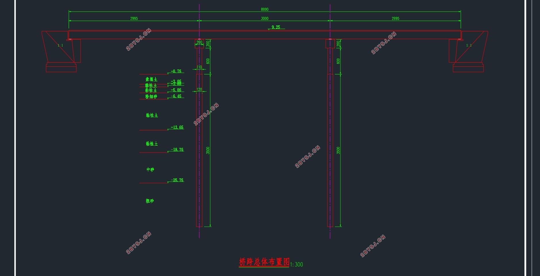
N8联全长90m,一联三跨,三跨跨度相等均为30m,桥面宽17.5m


目 录
摘要 1
Abstract 2
第1章 绪论 1
1.1研究背景 1
1.2毕业设计的目的与意义 2
第2章 设计资料 3
2.1设计标准 3
2.2设计资料 3
2.3技术规范 3
第3章 桥梁的方案设计 4
3.1桥梁线形布置 4
3.2材料选用 4
3.2.1. 混凝土 4
3.2.2 预应力钢筋 4
3.2.3普通钢筋 4
3.2.4其他材料 5
3.3箱梁结构尺寸设计 5
3.3.1截面类型确定 5
3.3.2梁高确定 5
3.3.3单箱双室截面细部尺寸的选择 5
3.4截面几何特性 7
3.5截面沿跨度方向变化 8
3.6桥面构造设计 8
第4章 Midas建模 9
4.1设置操作环境 9
4.2定义材料和截面 10
4.2.1定义材料 10
4.2.2定义截面 11
4.2.3定义变截面 14
4.3建立结构模型 14
4.3.1建立节点和单元 14
4.3.2定义变截面组 15
4.3.3定义结构组 16
4.3.4定义时间依存材料特性 16
4.3.5定义边界条件 16
4.4 Midas分析过程 21
4.5进行PSC设计 22
4.6 Midas验算 23
第5章 内力计算 42
5.1箱梁自重内力计算 42
5.2二期恒载内力计算 44
5.3汽车荷载作用效应计算 44
5.3.1 冲击系数和折减系数 44
5.3.2汽车荷载横向分布影响的增大系数计算 45
5.3.3汽车活载效应计算 45
5.4基础变位影响力 54
5.5荷载组合 56
5.5.1 按承载能力极限状态设计 56
5.5.2按正常使用极限状态设计 57
第6章 预应力钢束的估算及布置 60
6.1钢束估算 60
6.2 钢束布置 62
6.2.1 钢束布置构造要求 62
6.2.2 钢束布置原则 62
6.2.3 钢束起弯角和线型的确定 63
6.3箱梁横向预应力束设计 64
第7章 盖梁设计 66
7.1桥墩及盖梁尺寸 66
7.2盖梁荷载计算 66
7.2.1永久作用 66
7.2.2可变作用计算 67
7.2.3内力计算 69
7.3 盖梁配筋计算 69
7.3.1弯矩作用下的正截面配筋计算 69
7.3.2剪力作用时配筋计算 70
7.3.3 抗裂验算 70
第8章 桥墩设计与计算 72
8.1 荷载计算 72
8.1.1 恒载计算 72
8.1.2 活载计算 72
8.2截面配筋计算 72
8.2.1截面配筋设计 72
8.3墩柱截面承载力复核 74
第9章 桩基础计算 76
9.1地质资料 76
9.2荷载计算 76
9.3桩长计算 77
9.4桩的内力及位移计算 78
9.4.1基本假定 78
9.4.2计算宽度的确定 79
9.4.3桩的变形系数计算 79
9.4.4桩顶外力及最大冲刷线处(地面处)桩上外力计算 79
9.4.5最大冲刷线以下深度Z处桩截面上的弯矩 及水平应力 计算 79
9.4.6桩顶纵向水平位移验算 83
9.5 桩基配筋计算及桩身材料截面强度验算 83
参考文献 86
致谢 87
