TC6518型塔机臂架设计(含CAD零件图部装图)
无需注册登录,支付后按照提示操作即可获取该资料.
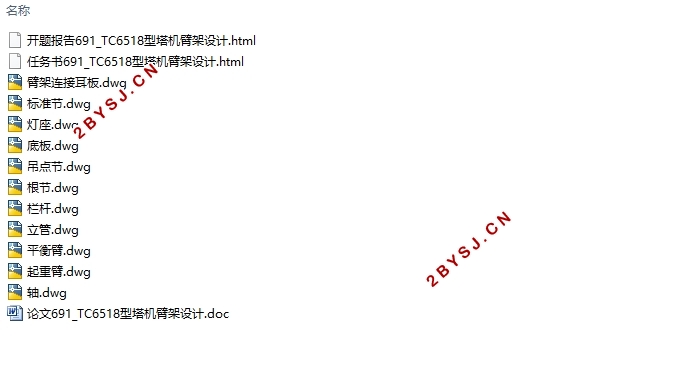
TC6518型塔机臂架设计(含CAD零件图部装图)(任务书,开题报告,论文说明书10300字,CAD图11张)
摘 要
在高层建筑和大型的货物搬运行业里,塔式起重机的存在是不可缺少的,并且逐渐向高速和专业定制的方向发展。臂架是塔机非常重要的工作部件,对于整个臂架的设计及其附属机构的选型都能直接影响到塔机的使用性能。
本文简要介绍了国内外塔式起重机的发展情况,结合材料力学、钢结构原理等知识,建立TC6518塔机起重臂和平衡臂简要的力学模型来进行辅助计算,列举了3种工况进行分析,画出了各个工况下的轴力、剪力、弯矩图,对所设计的臂架进行强度、刚度、稳定性校验。臂架与塔身的连接处采用公称直径为55mm 的平头带孔销轴,臂节间的连接选用公称直径M27的螺栓。最后对起升机构的组成部件进行计算选型,选择电动机型号为YZRSW280-4/8,减速器的型号为QJS280-25,制动器的型号为YWZ3-315/90-16。
关键词:起重臂 平衡臂 起升机构 稳定性
Design of Jib of TC6518 Tower Crane
Abstract
In high-rise buildings and large cargo handling industry, the existence of tower crane is indispensable, and gradually to the direction of high-speed and professional customization. The jib is a very important working part of the tower crane, so the design of the whole jib and the selection of its subsidiary mechanism can directly affect the performance of the tower crane.
There is the progress of tower crane domestic and foreign in this article,. Combined with the knowledge of material mechanics and steel structure principle, a brief mechanical model of lifting arm and balancing arm of TC6518 tower crane is established to carry out auxiliary calculation. Three working conditions are listed and analyzed. The diagrams of axial force, shear force and bending moment under each working condition are drawn, and the stiffness and stability of the designed jib are checked. The flat head pin with holes with nominal diameter 55mm is used to connect the boom with the tower body. The bolts of M27 are selected for the connection in the jibs.Finally, complete the reckon and type of lifting mechanism.The motor model is YZRSW280-4/8, the reducer model is QJS280-25, and the brake model is YWZ3-315/90-16.
Key words:Jib; counter weight jib; lifting mechanism; stability
起重臂的结构
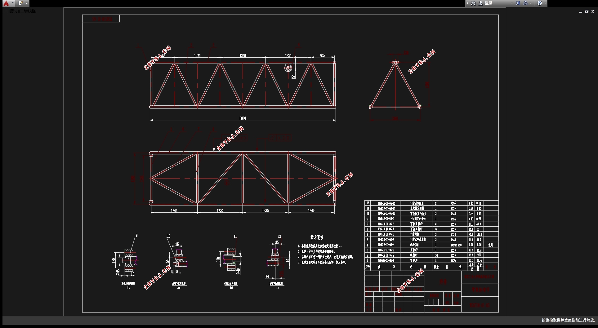
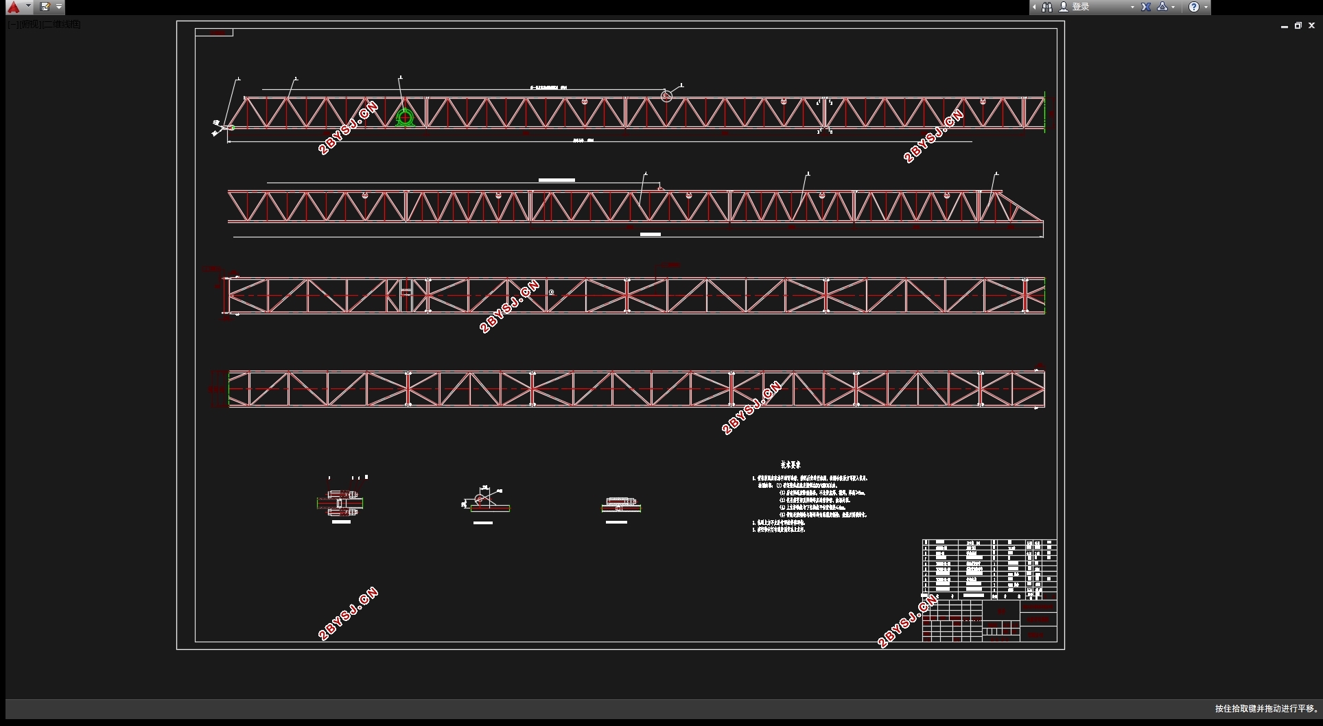
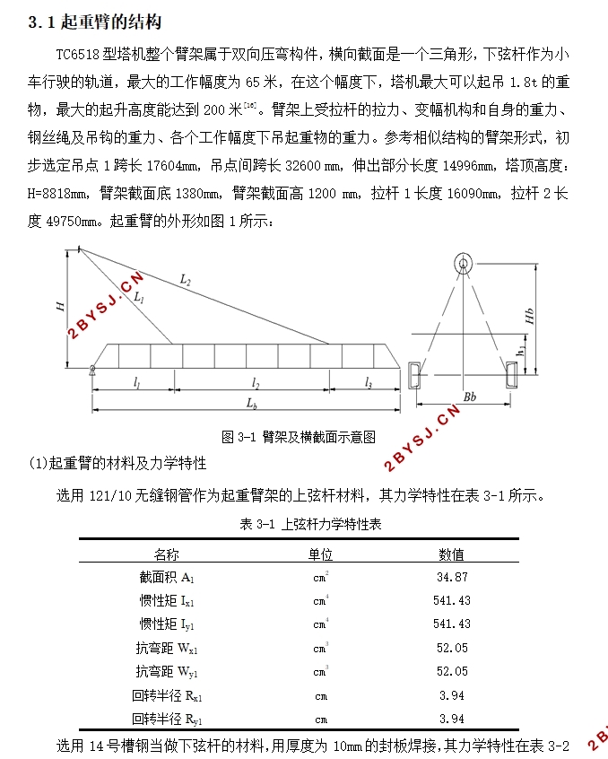
TC6518型塔机整个臂架属于双向压弯构件,横向截面是一个三角形,下弦杆作为小车行驶的轨道,最大的工作幅度为65米,在这个幅度下,塔机最大可以起吊1.8t的重物,最大的起升高度能达到200米[16]。臂架上受拉杆的拉力、变幅机构和自身的重力、钢丝绳及吊钩的重力、各个工作幅度下吊起重物的重力。参考相似结构的臂架形式,初步选定吊点1跨长17604mm,吊点间跨长32600 mm,伸出部分长度14996mm,塔顶高度:H=8818mm,臂架截面底1380mm,臂架截面高1200 mm,拉杆1长度16090mm,拉杆2长度49750mm。
目 录
摘 要 1
Abstract II
第一章 绪论 2
1.1 课题背景及意义 2
1.2 国外塔机的发展 2
1.3 国内塔机的发展 2
第二章 总体设计方案 4
2.1 臂架的设计 4
2.2 起升机构 4
第三章 臂架的设计 6
3.1 起重臂的结构 6
3.2 起重臂的载荷计算 8
3.3 起重臂架工况分析与校核 10
3.3.1 工况分析 11
3.3.2 起重臂刚度、稳定性校核 15
3.4 平衡臂的计算 24
3.4.1 平衡臂的构造 24
3.4.2 平衡重确定 26
3.4.3 平衡臂载荷计算 26
3.4.4 平衡臂刚度、稳定性校核 28
第四章 起升机构 30
4.1 钢丝绳的选型 30
4.2 卷筒设计 30
4.3 电动机计算选型 31
4.4 减速器选择 32
4.5 制动器选择 33
第五章 总结 34
5.1 总结 34
5.2 经济性分析 34
参考文献 35
致 谢 37
