宇通ZK6579校车制动系设计(含CAD零件装配图,CATIA三维图)
无需注册登录,支付后按照提示操作即可获取该资料.
宇通ZK6579校车制动系设计(含CAD零件装配图,CATIA三维图)(任务书,开题报告,外文翻译,文献摘要,论文说明书13000字,CAD图8张,CATIA三维图)
摘 要
随着现代人出行速度的日益提高,人们愈发关注汽车行驶安全性。制动系统作为汽车重要组成部分,直接影响整车安全性,可靠的制动系统是复杂道路行驶过程中的不可或缺的安全保障之一。
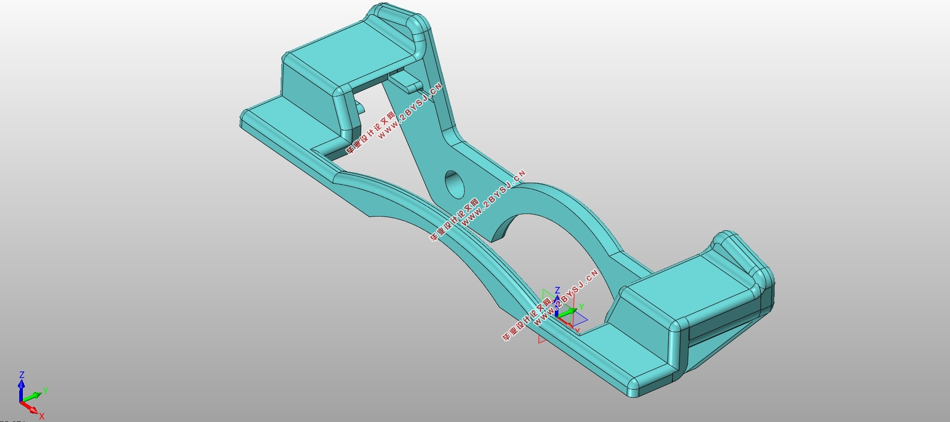
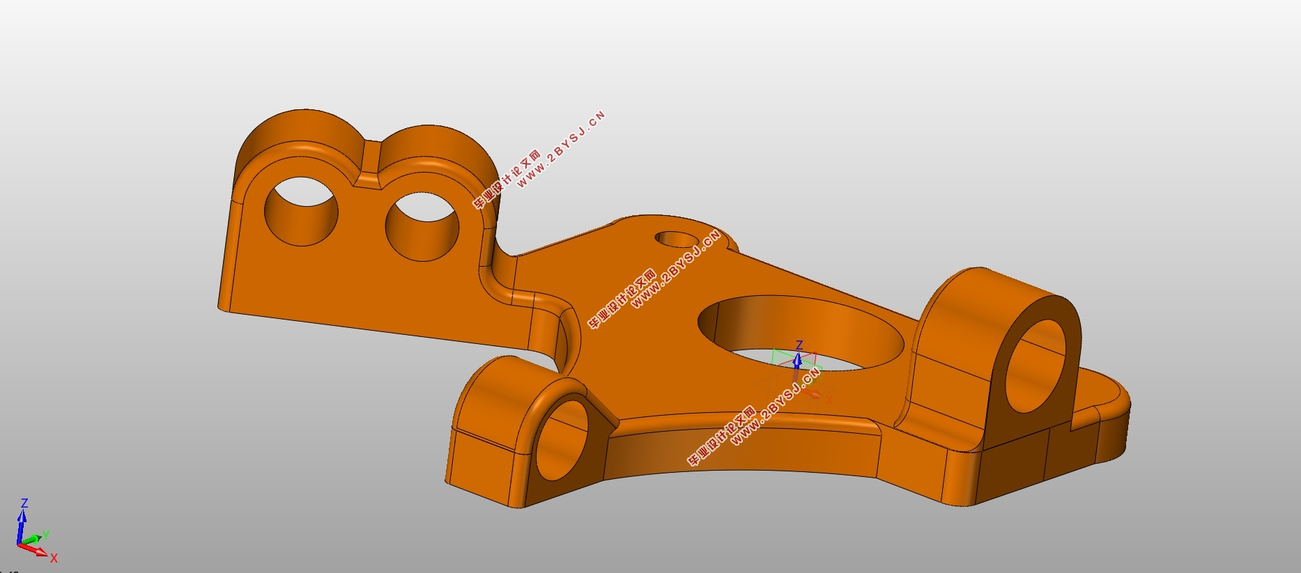
本设计着眼于校车这一特殊车种,旨在从给定的设计参数出发,设计出一套制动系统,有效地保障学生出行安全。本设计前后轮均采用的是盘式制动器,配合双管路的液压驱动机构和间隙自动调整装置,在保证较高的制动效能的同时,还能维持较高的稳定性。继而聚焦前轮,阐述了制动器的分类,进行比较,选择为浮动钳式盘式制动器,完成了该制动器主要零部件设计、驱动机构等相关计算。最后,生成三维模型、装配图和零件图。
关键词: 盘式制动器 液压驱动机构 双管路 间隙自动调整
Abstract
With the increasing speed of modern people's travel, people pay more and more attention to the safety of driving. As an important part of the car, the brake system is directly related to the safety of the whole vehicle. The reliable braking system is not suitable during the complicated road driving. One of the lack of security.
This design focuses on the special type of school bus. It aims to design a braking system based on the given design parameters to effectively ensure the safety of students. The front and rear wheels of the design are all disc brakes, combined with the hydraulic drive mechanism and automatic gap adjustment device of the double pipeline, which can maintain high stability while ensuring high braking performance. Then focus on the front wheel, explain the classification of the brakes, compare, finally select the floating clamp disc brake, complete the design of the main components of the brake, complete the relevant calculations of the drive mechanism. Finally, generate 3D models, assembly drawings, and part drawings.
Key words:Disc brake; hydraulic drive mechanism; double pipe; automatic adjustment of clearance

目录
摘 要 I
Abstract II
第1章 绪论 1
1.1制动系统设计相关介绍 1
1.1.1制动系统介绍 1
1.1.2制动系统的设计要求 2
1.2制动系统发展现状 3
1.3 校车制动系统设计特殊性 4
第2章 制动器的结构形式及选择 6
2.1 制动器的结构形式说明与分析 6
2.1.1液压鼓式制动器 6
2.1.2液压盘式制动器 7
2.2 浮钳盘式制动器的优点 9
第3章 制动系统主要参数的选择计算 11
3.1整车相关基本参数 11
3.2制动力分配系数 11
3.3制动强度与附着系数利用率 12
3.4制动器最大制动力矩 13
3.5制动器因数 14
第4章 盘式制动器的相关设计 15
4.1盘式制动器主要参数的确定 15
4.1.1制动盘 15
4.1.2制动钳 16
4.1.3制动块 16
4.1.4摩擦材料 16
4.1.5制动器间隙 16
4.2制动器制动力矩计算 17
4.3磨损特性的计算 17
4.4制动距离的计算 17
4.5驻车制动相关计算 18
第5章 制动驱动机构设计 20
5.1 制动驱动机构的形式与选择 20
5.2制动管路多回路系统设计 20
5.3 液压制动驱动机构的相关设计计算 21
5.3.1制动轮缸直径d的计算 21
5.3.2轮缸活塞宽度与缸筒壁厚计算 21
5.3.3制动主缸相关参数计算 22
5.3.4制动踏板力计算 23
5.4真空助力器相关介绍 24
结 论 26
参考文献 27
致 谢 29
