65t/66.5m岸桥梯形架设计及三维建模设计(含CAD总图,梯形架SolidWorks三维图
无需注册登录,支付后按照提示操作即可获取该资料.
65t/66.5m岸桥梯形架设计及三维建模设计(含CAD总图,梯形架SolidWorks三维图)(任务书,开题报告,论文说明书24000字,CAD图2张,梯形架SolidWorks三维图)
摘 要
岸桥作为起重运输机械中的重要一员,长期以来一直受到各方关注,其操作技术、运输能力及结构等也一直在专业人员的研究设计下更新换代以满足市场需求,达到更加高效、安全的目的。
本次设计以了解港口运输为基础,对岸桥的设计经验进行了归纳总结,并在这些基础上加入自己的理解,对岸桥进行整体设计并对梯形架部分进行结构设计。
本文严格按照《起重机设计规范》对岸桥进行设计校验。通过对重心矩法的运用,对岸桥进行了总体计算。同时利用虚功原理、图乘法等方法对梯形架结构部分进行了强度、刚度及稳定性的校验。
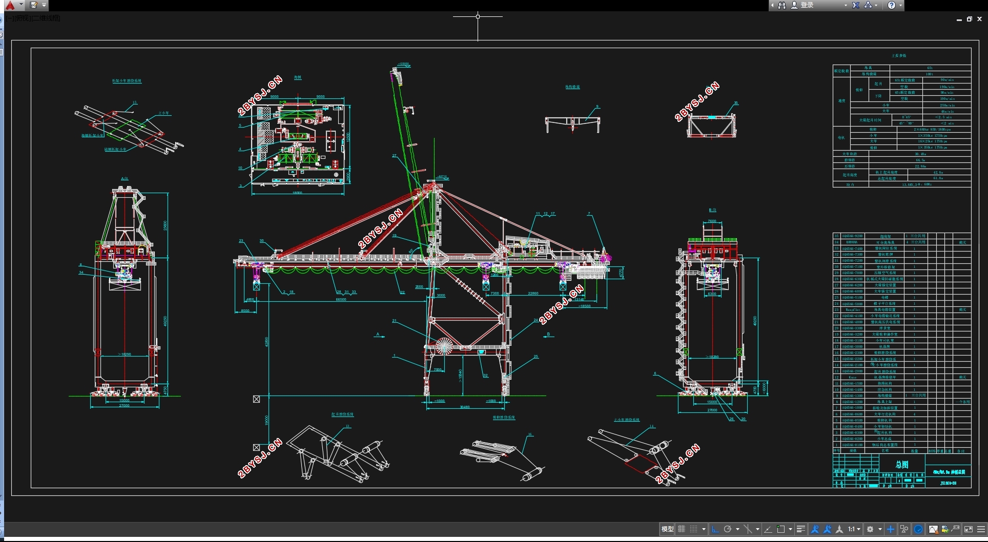
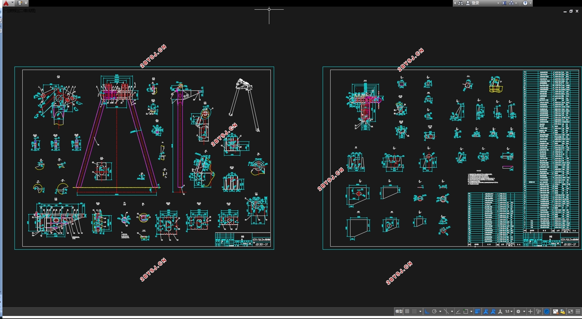
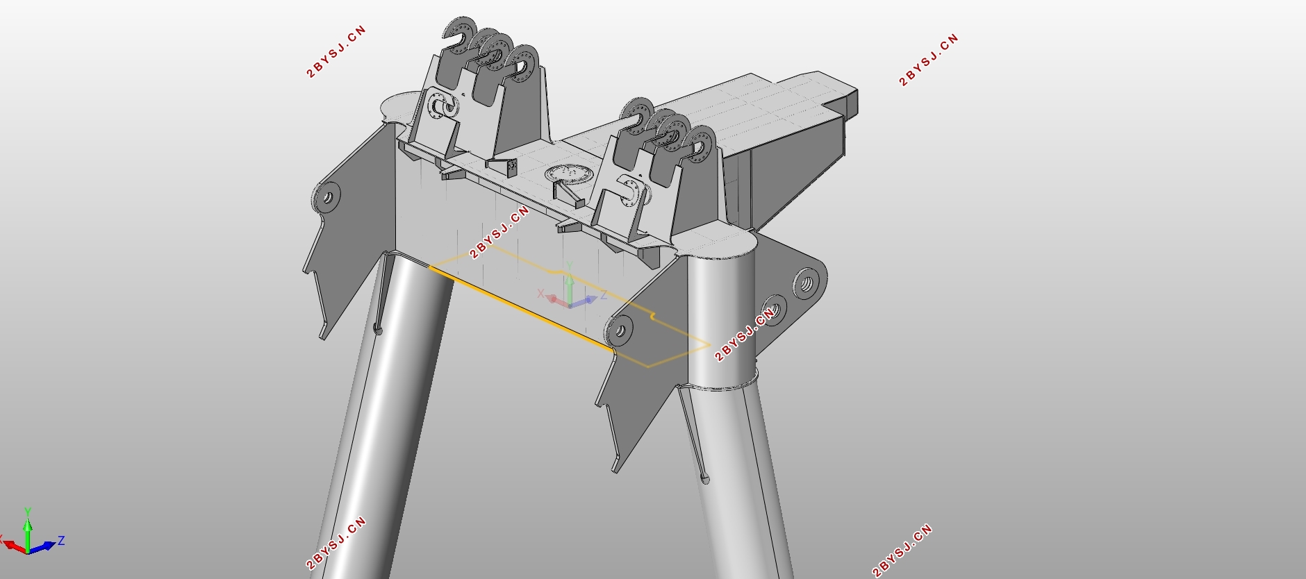
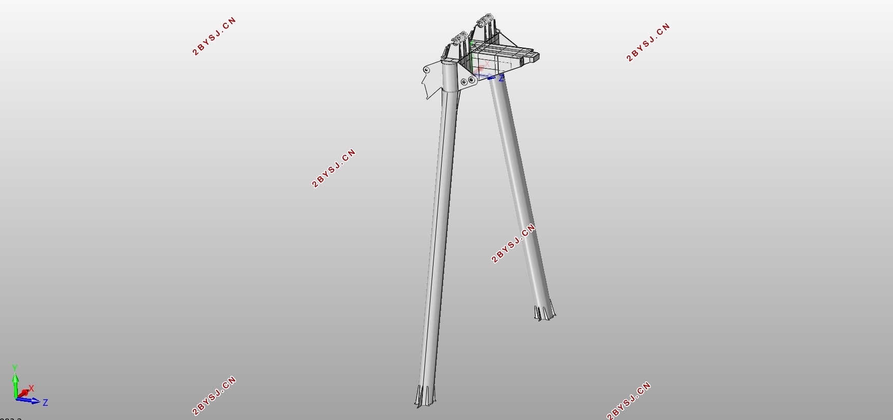
为了更直观并全面了解岸桥各部分结构及其相互之间的配合,在进行计算的同时还利用CAD、SolidWorks等绘图软件对岸桥总图进行绘制,同时对梯形架部分进行了三维建模。相较于以往的计算说明本文更加具有针对性。三维模型的建立也更利于发现在设计过程中出现的问题并及时加以修改。
经过一系列的计算,岸桥的设计符合要求。
关键词:岸桥;梯形架;结构设计;载荷计算
Abstract
As an important member of the lifting and transportation machinery, the container crane has been paid attention to by the parties for a long time. Its operation technology, transportation capacity and structure have also been renewed under the research and design of professionals to meet the market demand and achieve the purpose of more efficient and safety.
This design is based on the understanding of port transportation, summarizes the experience of the design of the container crane, and on this basis to join my understanding, the overall design of the container crane and the pylon of the structural design.
This article in strict accordance with the "crane design specifications" on the container crane design verification. Through the use of the center of gravity method, the overall calculation of the container crane. At the same time, the strength, stiffness and stability of the pylon structure are verified by the principle of virtual work and multiplication.
In order to more intuitive and comprehensive understanding of the structure of the various parts of the quarry and their cooperation with each other, while the use of CAD, SolidWorks and other mapping software to draw the total map of the container crane, while the trapezoidal part of the three-dimensional modeling. This is more relevant than the previous calculations. The establishment of the three-dimensional model is also more conducive to the discovery of the design process problems and timely changes.
After a series of calculations, the design of the container crane meets the requirements.
Key Words:container crane;pylon;structural design;Load calculation
主要参数(m)
前伸距 66.5
后伸距 22.86
大车轨距S 30.48
大车基距B 14.5
无束缚



目 录
第1章 绪论 1
1.1 研究背景及目的 1
1.2 与课题相关国内外发展现状 1
1.3课题研究内容 2
第2章 起重机重量及重心的计算 3
2.1 固定件重量和作用在整机的重心 4
2.1.1 机器房 4
2.1.2 结构固定部分 7
2.1.3 固定件重量及重心合成 8
2.2 俯仰部分重量和作用在整机的重心 11
2.3 固定载荷及作用在整机的重心 14
2.4 小车自重载荷及起吊系统载荷作用在整机的重心 16
2.4.1 小车自重载荷 16
2.4.2 起吊系统载荷 18
2.5 起重机总重及整机重心 20
2.5.1 操作位 20
2.5.2 锚定位 20
2.5.3 维修位 20
2.5.4 停机位 20
2.6 起升载荷及作用重心 21
2.7 偏心起吊负荷 22
第3章 惯性载荷计算 23
3.1 大车运行起制动时的惯性载荷 23
3.1.1 大梁水平 23
3.1.2 大梁仰起45° 25
3.1.3 大梁仰起80° 25
3.2 小车运行起制动时的惯性载荷 26
3.2.1 惯性载荷平行于大车轨道 26
3.2.2 惯性载荷垂直于大车轨道 27
3.3 地震载荷 28
3.3.1 地震载荷平行于大车轨道 28
3.3.2 地震载荷垂直于大车轨道 30
3.4 起升时的垂直冲击载荷 31
3.5 碰撞载荷 31
3.5.1 大车碰撞载荷 31
3.5.2 小车碰撞载荷 32
3.6 失速载荷 33
第4章 风载荷计算 34
4.1 工作状态下风载荷 34
4.1.1 大梁水平 34
4.1.2 大梁仰起45° 39
4.1.2 大梁仰起80° 42
4.2 非工作状态下风载荷 44
4.2.1 大梁仰起45° 45
4.2.2 大梁仰起80° 47
第5章 载荷组合及腿压计算 51
5.1 工作状态载荷组合及腿压汇总 51
5.1.1 WOP1 51
5.1.2 WOP2 53
5.1.3 WOP3 54
5.1.4 WOP4 55
5.1.5 WOP5 57
5.2 非工作状态载荷组合及腿压汇总 58
5.2.1 WSM1 58
5.2.2 WSM2 59
第6章 稳定性校验 61
6.1 工作状态稳定性校验 61
6.1.1 ST1O 61
6.1.2 ST2O 63
6.1.3 ST3O 65
6.1.4 ST4O 66
6.2 非工作状态稳定性校验 68
6.2.1 ST1S 68
6.2.2 ST2S 69
6.2.3 ST3S 69
第7章 梯形架结构计算 71
7.1 力学模型简化 71
7.2 强度校核 72
7.2.1 弯矩计算及弯矩图绘制 72
7.2.2 截面特性计算 73
7.2.3 强度验算 75
7.3 刚度校核 77
7.3.1 小车在后大梁 77
7.3.2 小车在前大梁 78
7.4 稳定性校核 79
第8章 梯形架SolidWorks三维建模 80
第9章 环境影响和经济性分析 84
9.1 环境影响 84
9.2 经济性分析 84
第10章 总结与展望 86
10.1 总结 86
10.2 展望 86
参考文献 87
致谢 88
