马具连接架塑件成型工艺分析与模具设计(含CAD零件图装配图,PROE三维图)
无需注册登录,支付后按照提示操作即可获取该资料.
马具连接架塑件成型工艺分析与模具设计(含CAD零件图装配图,PROE三维图)(任务书,开题报告,外文翻译,论文说明书12000字,CAD图22张,PROE三维图)
摘要
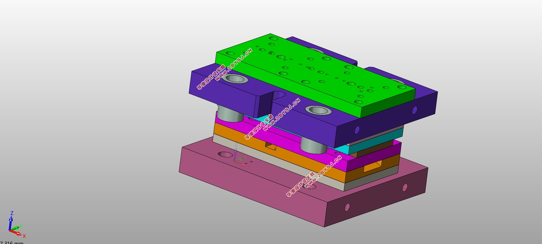
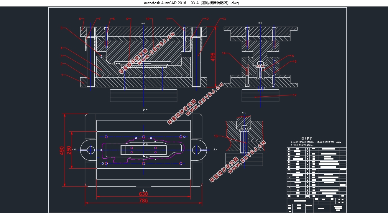
本课题研究内容是马具连接架塑件成型工艺分析与模具设计,针对塑件特定的结构进行分析与设计,通过制图软件制作所需总装图与各零件图。本学期课题作业时,首先通过查阅文献等途径了解注塑模具设计方案思路,之后使用PRO/E三维模型软件来制造塑件3D实体,并使用auto cad二维模型软件来制作所需总装图与各零件图。通过分型面的设计、侧向抽芯机构设计、导向机构设计、浇注系统设计以及脱模装置设计等等,实现各自的功能,并且进行装配完成完整模具,实现马具连接架塑件成型工艺分析与模具设计。
关键词:塑件;PRO/E;auto cad;模具设计;零件图;装配图
Abstract
This topic research content is the harness connection frame plastic molding technology analysis and die design, in view of the structure of the specific analysis and design, through mapping software make the assembly diagram with the part drawing.This semester's project work, the first through the way such as the literature about injection mould design train of thought, after using PRO/E software to create 3D model plastic parts 3D entity, and the use of auto cad 2D model software to make the assembly diagram and the part drawing.Through the parting surface design, side core-pulling mechanism design, design of steering mechanism, gating system design, and demolishing device design, etc., to realize their respective functions, and are assembled to accomplish the complete mold, connect harness in plastic molding technology analysis and die design.
Key words:Plasticpart;PRO/E;auto cad;Mold design;Part drawing;Assembly drawing
原料工艺分析
本塑件原料是ABS塑料。ABS是一种性能优良的原料之一,在注塑模具中经常使用。在注塑过程中,原料应该具有良好的流动性与耐热性能,便于充型,避免原料失效。ABS具有优越的综合性能,在低温状态下机械性能比其它材料有明显的优势,并且其电性能等物理性能也比较优越,能够满足使用要求,生产的制品也能够满足技术要求。其明显的优势导致ABS塑料的应用非常广泛,并且经常用于制造各种机械零件以及其它部件。
塑件工艺分析
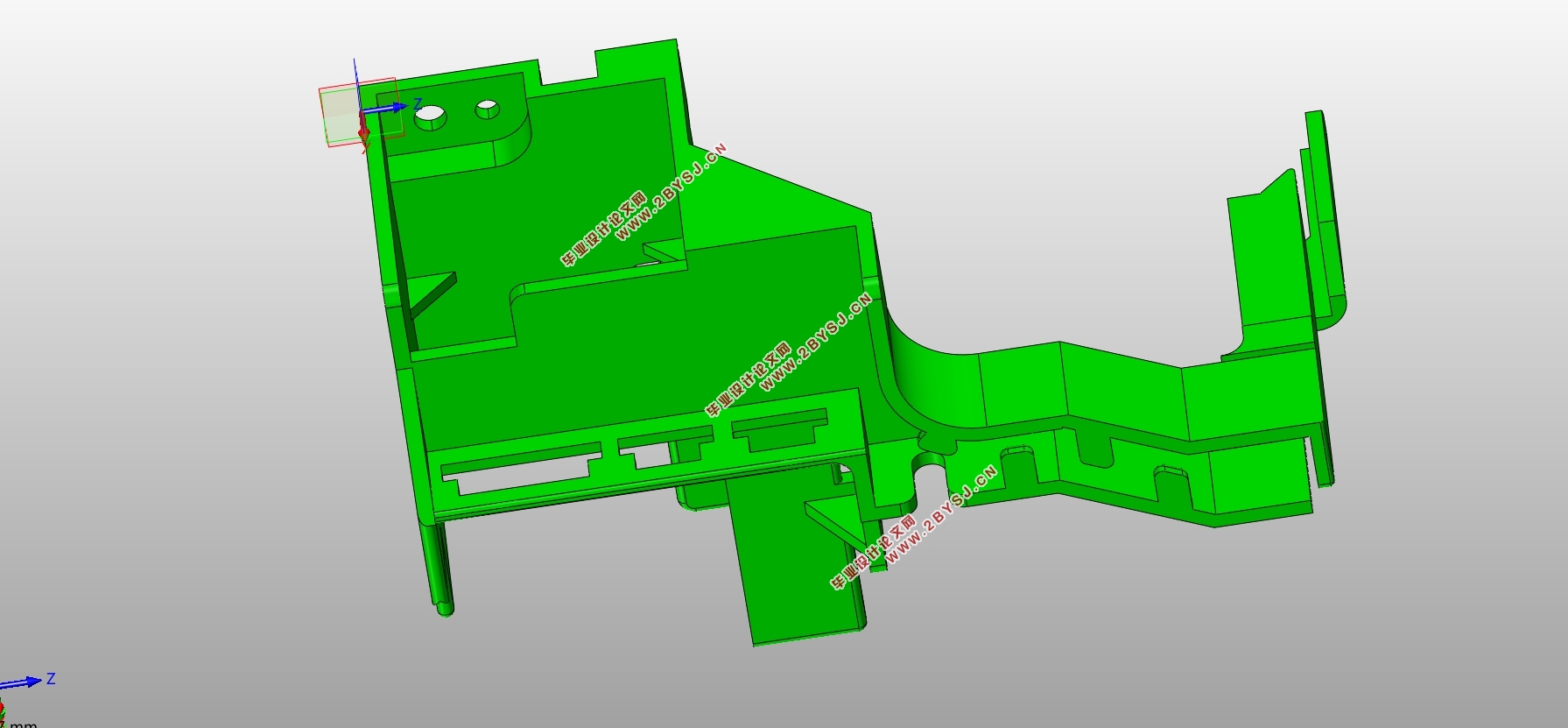
设计的零件是马具连接架塑件,厚度为2毫米,属于薄壁小型塑件。使用PRO/E在类型“零件”中选择实体,绘制壳体零件三维模型,通过参数化设计并根据得自工厂的零件图,先绘制主体,并且在主体的基础上逐步绘制各个特征,之后按照一定形状进行一定深度打孔,最终得到壳体零件,如图2.2所示。在PRO/E中选择模具型腔后,导入后创建工件,之后设置收缩,收缩方式为按比例收缩,由于原料是ABS,收缩率设置为百分之零点五,并且设置拔模斜度为一度,此时在工作目录中就存在考虑收缩的塑件三维模型。


目录
第一章绪论 1
1.1 国内外注塑模具发展现状 1
1.2 设计的目的和意义 1
1.3PRO/E和auto cad的应用 2
第二章塑件工艺分析 3
2.1 原料工艺分析 3
2.2 塑件工艺分析 3
第三章 型腔数量与排布 5
3.1 型腔数量 5
3.2 型腔排布 5
第四章 注射机选型与校核 6
4.1 注射机的类型选择 6
4.2 注射机的型号选择 6
4.3 注射机的校核 6
第五章 模具设计 7
5.1 总体技术方案 7
5.2 模架选用 7
5.3 浇注系统 8
5.3.1 浇注系统选型 8
5.3.2 浇注系统设计 8
5.4 脱模机构 9
5.4.1 推出装置 9
5.4.2 非推出装置 10
5.5 侧向抽芯机构 11
5.5.1 侧向抽芯机构选型 11
5.5.2 侧向抽芯机构组成 12
5.5.3 侧向抽芯机构设计 12
第六章 模具装配图和零件图 14
6.1 模具装配图 14
6.2 模具零件图 15
参考文献 17
致谢 18
