
固定连接件(汽车后防撞梁连接板)工艺分析及模具设计(含CAD零件装配图)
无需注册登录,支付后按照提示操作即可获取该资料.
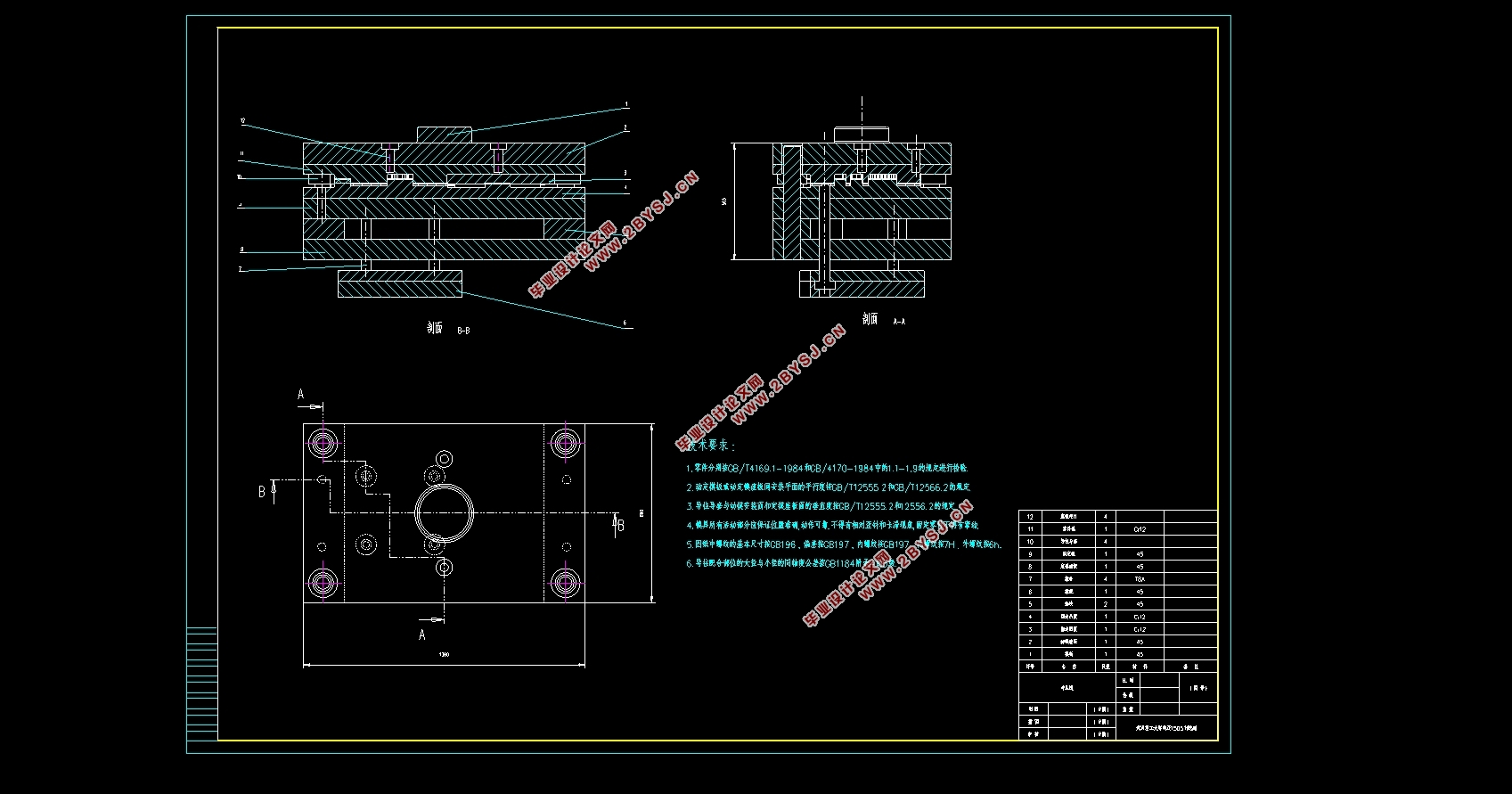
固定连接件(汽车后防撞梁连接板)工艺分析及模具设计(含CAD零件装配图)(任务书,开题报告,外文翻译,论文说明书12000字,CAD图2张)
摘要
本次的毕业设计内容是后防撞梁连接板工艺分析及模具设计,该零件是一种形状较为简单的汽车板材零件,对于了解汽车冲压件的设计有一定的意义。在查阅相关的资料之后,我决定采用级进模生产。在设计时我考虑的主要内容包括:1.冲压件的工艺分析;2.冲压件冲压工艺过程的确定;3. Autoform数值模拟仿真;4.后防撞梁连接板的模具设计;5.模具图纸的绘制。在这一系列工作内容的锻炼下,对冲压模具的整体结构有了充分的了解,熟悉了汽车冲压件的生产流程,并且学会了熟练使用AutoCAD。本次设计,让我在模具设计、模具成型工艺分析、资料查阅等方面的能力有了极大的提高。面对设计中遇到的困难,也在老师的帮助下一一解决,最终保质保量的完成了汽车后防撞梁连接板的冲压模具设计。
关键词:模具,冲压,连接板,级进模
Abstract
This graduation project is about the process analysis and die design of the rear anti-collision beam connecting plate. This part is a simple automobile plate part, which has a certain significance for understanding the design of automobile stamping parts. After consulting the relevant information, I decided to adopt progressive die production. The main contents I considered in the design include: 1. Process analysis of stamping parts; 2. Determination of stamping process of stamping parts; 3. Autoform numerical simulation; 4. Die design of rear anti-collision beam connecting plate; 5. Drawing of die drawings. In this series of work, I have a full understanding of the overall structure of the stamping die, familiar with the production process of automobile stamping parts, and learned to skillfully use AutoCAD. This design has greatly improved my ability in die design, die forming process analysis, data access and so on. Facing the difficulties encountered in the design, with the help of the teacher, the stamping die design of the connecting plate of the rear anti-collision beam of the automobile was finally completed with high quality and quantity.
Keywords: mold, stamping, Connecting plate,Progressive die
零件的材料分析
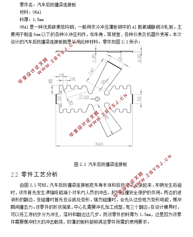
零件名:汽车后防撞梁连接板
材料:08Al
料厚:1.5mm
08Al是一种优质碳素结构钢,一般用作冷冲压薄板钢中的Al脱氧镇静钢冷轧板。主要用于制造6mm以下的各种冷冲压构件,如车身、驾驶室、各种仪表及机器外壳等。本次设计的汽车后防撞梁连接板就是采用此种材料。


目 录
第1章绪论 1
1.1选题的意义与目的 1
1.2 文献综述 1
1.3 研究现状 1
1.4 设计思路与创新思路 2
第2章零件的冲压工艺分析 3
2.1 零件的材料分析 3
2.2 零件工艺分析 3
2.2.1 精度的确定 4
2.2.2 粗糙度的确定 4
2.2.3 工艺路线的制定 4
2.3 零件成型分析 5
2.3.1 冲压CAE分析的目的 5
2.3.2 AutoForm的分析设置 6
2.3.3 结果分析 10
2.4 排样设计 11
2.4.1 排样原则 11
2.4.2 整体排样设计 11
2.5 本章小结 11
第3章零件模具的工艺计算 13
3.1 压力中心的确定 13
3.2 凸模与凹模刃口尺寸计算 13
3.2.1 刃口尺寸计算原则 13
3.2.2 凸凹模刃口尺寸计算 13
3.3 冲压工艺力计算 16
3.3.1 冲裁力的计算 16
3.3.2 卸料力、顶件力和推料力的计算 17
3.4 各主要零件尺寸计算 17
3.4.1 凹模厚度 17
3.4.2 凸模固定板的选用与厚度 19
3.4.3 卸料零件的设计 19
3.5 本章小结 20
第4章总体结构设计及零部件选用 21
4.1 模具主要零部件的设计 21
4.1.1 冲裁凸凹模的设计 21
4.1.2 卸料板的设计 23
4.3 冲床选用 24
4.3.1 冲压设备的选择依据 24
4.3.2 压力机的选择 24
4.4 模具的总体结构设计 24
4.5 本章小结 25
第5章模具材料的选用 26
第6章模具的装配与检测 27
6.1 模具的装配 27
6.2 模具的检测 27
第7章设计经济性及环保性分析 28
7.1 经济性分析 28
7.2 环保性分析 28
总结 29
参考文献 30
致谢 31