基于UG NX的旋盘件侧抽芯模具设计(含CAD图,CAXA图,UG三维图)
无需注册登录,支付后按照提示操作即可获取该资料.
基于UG NX的旋盘件侧抽芯模具设计(含CAD图,CAXA图,UG三维图)(论文说明书9000字,CAD图4张,CAXA图4张,UG三维图)
摘 要
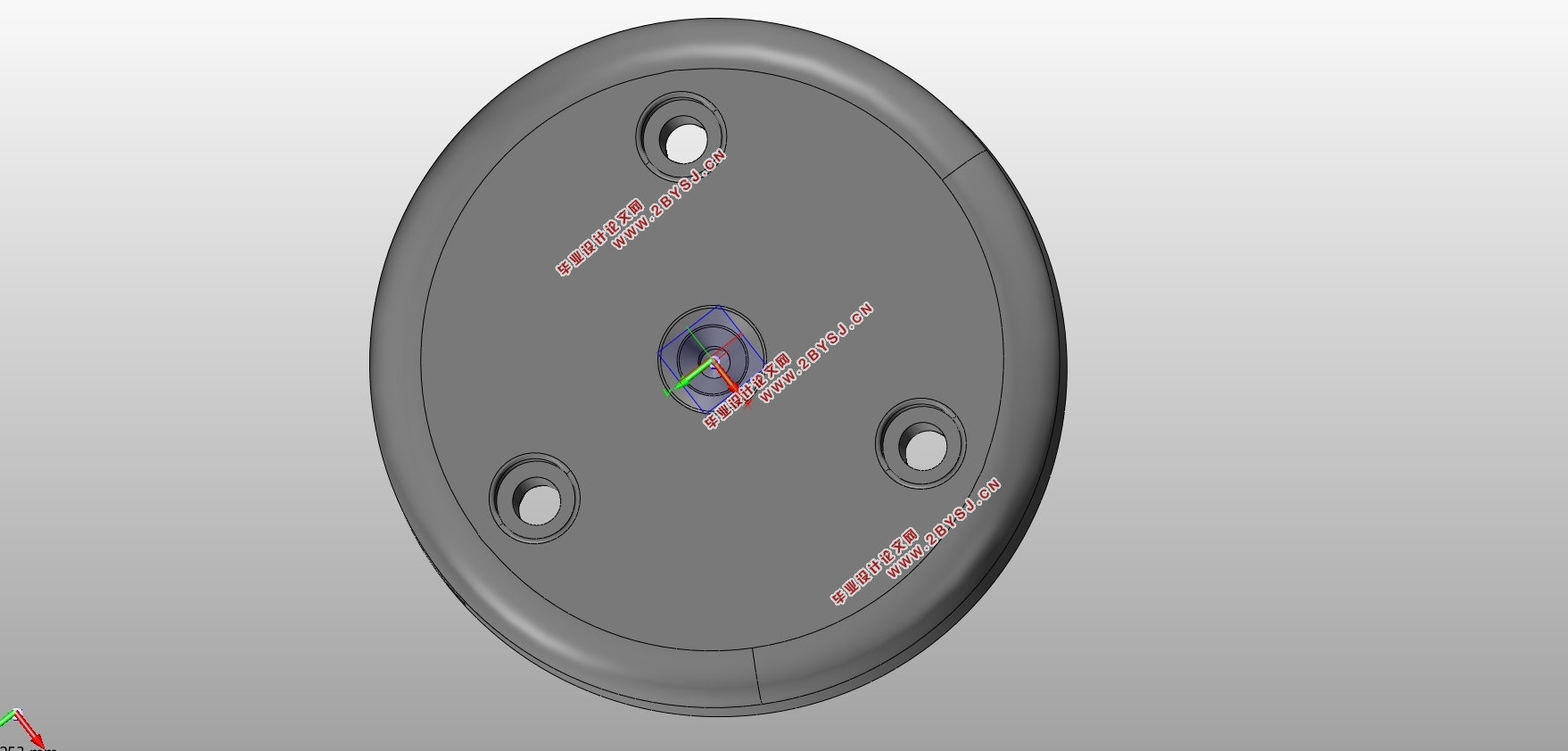
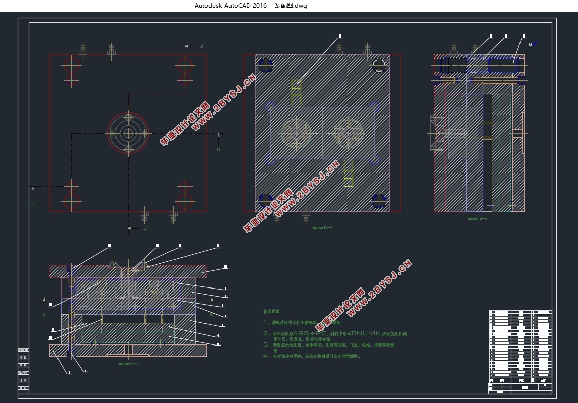
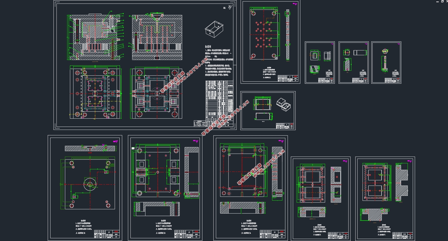
此设计是基于NX的旋盘件侧抽芯模具设计,设计的总体部分可以大致分为分型面的选择、侧向抽芯的设计、模架的选择、浇注系统的设计、冷却系统的设计、脱模系统的设计。本次设计的要点:此设计在注塑成型时,型腔内壁有一个凸台,必须要使用侧抽芯,以便于零件的成型和脱模。型腔的内侧有一个阶梯状的凸起,需要进行镶块设计。因为在实际生产中会对型腔形成冲刷,阶梯状的结构形成的型腔就容易损坏,因此需要设计镶块以便于更换和减少制造成本。此次设计最重要的一点就是更清楚的表达模具的内部结构,因此会附上设计时保存的结构图,局部放大图,还有模具的爆炸图。
关键词:塑件设计;旋盘式零件;侧抽芯设计
Abstract
This design is based on the NX side core pulling mold design, the overall part of the design can be roughly divided into parting surface selection, side core pulling design, mold base selection, pouring system design, cooling system design, demoulding system design. Key points of this design: during the injection molding, there is a boss on the inner wall of the cavity, so side core pulling must be used to facilitate the molding and demolding of parts. There is a stepped bulge on the inner side of the cavity, which needs to be inlaid. Because the cavity will be scoured in the actual production, the cavity formed by the stepped structure is easy to be damaged, so it is necessary to design inserts to facilitate replacement and reduce manufacturing costs. The most important point of this design is to express the internal structure of the mold more clearly. Therefore, the structural drawing, partial enlarged drawing and exploded drawing of the mold saved in the design will be attached.
Key words:plastic part design; Rotating disc parts; side core pulling design
塑件的结构分析
首先,塑件的形状、尺寸、壁厚及表面特征等对成型加工的适应性,其次在满足力学性能的基础上还要方便模具的设计以及塑件的成型加工。除了必要的抽芯部分,尽量不要采用抽芯结构,这样可以减少制造成本和减少设计工作量。此外盘类零件有共同的特点零部件结构不太复杂,主要为同轴度要求较高的内外旋转表面;多为薄壁件,容易变形。
参考实物所设计的零件图
然后对产品的壁厚进行分析,平均壁厚为2.5mm,最大壁厚约3mm符合成型要求。再进行产品的面分析检查,面分析检查是手动分模的重要步骤,一是为了去找分型面,二是为了在产品的直身面去增加适当的拔模.设置的角度在 之间。


目录
第一章 绪论 5
1.1选题的背景 5
1.2国内外模具研究的动态 5
1.2.1国内模具研究动态 5
1.2.2国外模具研究动态 6
第二章 盘类零件模具前期设计 7
2.1塑件的工艺性分析 7
2.1.1塑件的结构分析 7
2.1.2塑件材料的选择 8
2.2注射成型机的选择及型腔数量的确定 9
2.2.1注射成型机的原理 9
2.2.2注射成型机的选择 9
第三章 旋盘件侧抽芯模具设计 11
3.1塑件手动分模 11
3.2创建侧向抽芯机构 12
3.3模具模架的选择 15
3.4镶块的设计 16
第四章 浇注系统的设计 17
4.1浇注系统的组成 17
4.2主流道和分流道的设计 17
4.2.1主流道设计要点: 17
4.2.2分流道设计要点 17
4.3定位环和浇口衬套的设计 18
第五章 冷却系统的设计 19
5.1冷却水道直径的设计 19
5.2冷却水道的设计要点 19
5.3冷却系统设计的具体步骤 20
第六章 顶出系统的设计 21
6.1推出力的计算 21
6.2推杆设计的具体步骤 21
第七章 排气系统的设计 22
7.1排气系统的作用 22
7.2容易困气的位置 22
7.3排气系统设计原则 22
7.4注塑模具的排气方式 23
第八章 模具设计成果图展示及总结 24
8.1部分成果图展示 24
8.2旋盘式侧抽芯模具设计总结 28
致谢 29
参考文献 30
