基于NX的手机前后盖薄壁件多件注塑模设计(含CAXA图,UG三维图)
无需注册登录,支付后按照提示操作即可获取该资料.
基于NX的手机前后盖薄壁件多件注塑模设计(含CAXA图,UG三维图)(论文说明书9000字,CAXA图5张,UG三维图)
摘 要
在本次的毕业设计中,我主要的设计任务是通过UG对手机前后盖薄壁件进行多件注塑模设计。我们都知道,手机在我们的日常生活中应用非常广泛,以前的手机大部分都是塑料外壳,由前后盖拼接而成,而现在手机种类多种多样,但塑料外壳仍然广泛应用。由此,本次我的设计任务是手机前后盖薄壁件的多件注塑模设计。
如今,社会经济发展迅速,现代工业也在不断发展,塑件制品越来越广泛,我们离不开塑件制品。由此,社会对模具设计人员需求量不断加大,UG软件的应用也十分重要,因此,我们必须学会它,学好它。
关键词:UG;手机前后盖;注塑模;
ABSTRACT
In this graduation project, my main design task is to carry out multiple injection mold design for thin-wall parts of the front and rear covers of the mobile phone through UG. As we all know, mobile phones are widely used in our daily life. In the past, most mobile phones were made of plastic shell, which was made by splicing the front and back covers. Now there are many kinds of mobile phones, but plastic shell is still widely used. Therefore, my design task this time is to design multiple injection mold for thin-wall parts of the mobile phone.
Nowadays, social economy develops rapidly, modern industry also is developing ceaselessly, plastic product is more and more extensive, we cannot leave plastic product. Therefore, the social demand for mold designers is increasing, UG software application is also very important, therefore, we must learn it, learn it.
Key words: UG; Front and rear cover; Injection mold;
塑件结构分析
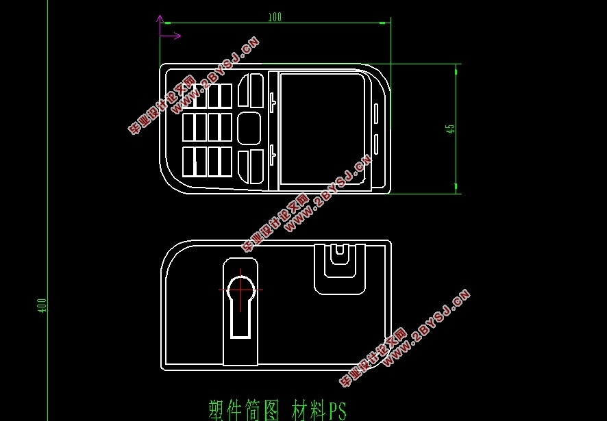
手机前后盖的长度为100mm,宽度为45mm,前盖厚度为2mm,后盖厚度为1mm。手机前后盖壁厚最厚处达2mm,在该模具设计过程中,需要考虑以下问题。
(1)浇口的设计与塑件形状、断面尺寸、模具结构、注塑工艺条件(压力)及塑料性能等因素有关。根据浇口的基本作用,浇口的截面要小,长度要短。由于材料采用PS塑料,虽然它的流动性很好,但其凝固时间很短,因此浇口的位置非常重要。
(2)模型模具要求实现一模两腔,即一次浇注同时成型手机的上盖和下盖。


目 录
第一章 绪论 1
1.1国内外模具研究现状 1
第二章 手机前后盖模具的前期设计 2
2.1塑件产品分析 2
2.1.1塑件材料分析 2
2.1.2塑件结构分析 2
2.2模具设计分析 3
2.2.1分型面的确定 3
2.2.2型腔数量的确定和排列方式 3
2.3注塑机型号的确定 3
2.3.1注射量的确定 3
2.3.2注塑机型号的选择 3
2.3.3型腔数量及注射机有关工艺参数的校核 5
第三章 型芯型腔的设计计算 7
3.1型芯尺寸计算 7
3.1.1前盖的型芯尺寸计算 7
3.1.2后盖的型芯尺寸计算 7
3.2型腔尺寸计算 8
3.2.1前盖的型腔尺寸计算 8
3.2.2后盖的型腔尺寸计算 9
第四章 型芯型腔的设计步骤 10
4.1项目初始化 10
4.2模具坐标系 10
4.3设置收缩率 11
4.4设置工件 12
4.5多腔模的设置 13
4.6手机前盖分型前的设置 13
4.7布局 14
4.8分型手机后盖 15
第五章 模架设计的计算 28
5.1模架的选择 28
5.2标准件的选择 28
5.3冷却水路的计算 28
第六章 模架的设计步骤 29
6.1添加模架 29
6.2添加标准件 29
6.3顶杆后处理 33
6.4设计填充 33
6.5添加冷却管道 34
6.6建立腔体 37
第七章 运动分析 38
7.1创建连杆 38
7.2创建运动副 39
7.3运动仿真 42
第八章 设计总结 43
8.1设计成果 43
结束语 49
致谢 50
参考文献 51
