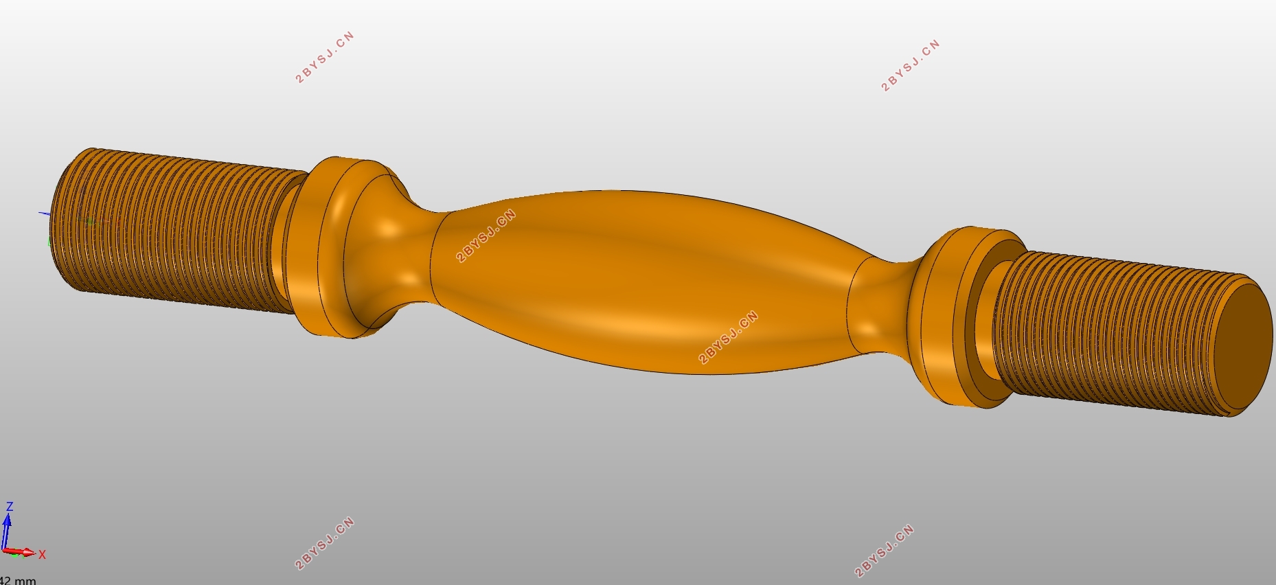
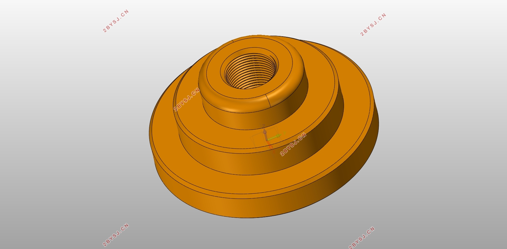
轴套类零件的加工工艺及设计(含CAD图,UG三维图,程序)
无需注册登录,支付后按照提示操作即可获取该资料.
轴套类零件的加工工艺及设计(含CAD图,UG三维图,程序)(论文说明书11000字,CAD图2张,UG三维图,程序)
摘 要
随着科技的进步,数控加工技术在制造行业中运用也越来越广泛了。本次设计主要是通过对数控加工的特点,对加工零件的外形进行工艺分析,选择合理的加工方法设计出零件的加工工艺过程,体现出数控加工的高效率、高精度、低成本、高质量的特点。设计说明书通过加工的零件以数控机床加工为基础,通过加工零件的材料、外形轮廓、加工精度等选择合理的数控加工机床。确定合理的加工方案,合理的安排加工顺序,选择合适的加工刀具、夹具的选择和切削量的确定,通过UG编程模块对零件进行零件的编程。在编程过程中,反复的对刀路进行和切削量进行合理的设置,通过加工仿真进行确认。根据任务书编写说明书,将设计加工零件的数据进行核对计算再进行分析,并在说明书上写出加工过程中的主要事项。
关键词:工艺分析,数控加工,切削用量,UG。
Abstract
With the progress of science and technology, the application of NC machining technology in manufacturing industry is more and more extensive. This design is mainly based on the characteristics of NC machining, process analysis of the shape of processing parts, select reasonable processing methods to design the processing process of parts, reflecting the characteristics of high efficiency, high precision, low cost and high quality of NC machining. According to the design specification, the parts processed are based on the CNC machine tool, and the reasonable CNC machine tool is selected through the material, contour and processing precision of the parts. Determine the reasonable processing scheme, reasonable arrangement of processing sequence, select the appropriate cutting tool, fixture selection and cutting amount determination, through the UG programming module for parts programming. In the process of programming, the tool path and cutting amount are set repeatedly and confirmed by machining simulation. According to the task book, write the instruction, check and calculate the data of the designed and processed parts, and then analyze them, and write out the main items in the process of processing in the manual.
Key words: process analysis, NC machining, cutting parameters, UG.
3.1毛坯的选择
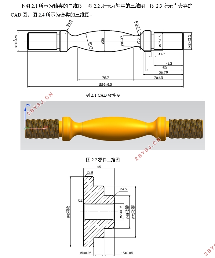
该组合件为轴类零件,故其毛坯选择为棒料,毛坯材料为45钢,根据零件的形状选择毛坯:轴类尺寸为φ40x225mm的圆棒料;套类尺寸为φ105x50mm的圆棒料。
3.2定位基准的选择
在数控机床加工过程中要是没有统一的定位基准,在进行二次装夹加工时会造成零件的位置和尺寸的偏差。必须在零件上选择合适的结构作为定位基准,必可以使用工艺结构、精加工表面作为统一基准来减少二次加工的误差。
①确定该轴类粗基准为:φ40mm的毛坯外圆;精基准为:车削好的φ32mm外圆。
②确定该套类粗基准为:φ105mm的毛坯外圆;精基准为:车削好的φ48mm外圆。
3.3装夹方式的选择
主要分析考虑毛坯的装夹定位和夹紧,装夹的方便和可靠性,有利于加工多个面时方便进行装夹。
经分析,该组合零件的毛坯均为圆棒料,此次装夹时以毛坯外轮廓定位,采用三爪卡盘进行装夹,


目 录
摘 要 3
Abstract 4
第一章 绪 论 1
1.1数控加工的简介 1
1.2数控加工技术的发展趋势 1
1.3我国数控工业的发展方向 1
第二章 基于UG的三维造型设计 3
2.1零件CAD结构形状图 3
2.2轴类零件三维造型设计 4
2.2.1进入初始界面 4
2.2.2新建模型 5
2.2.3绘制步骤 5
2.3套类零件三维造型设计 8
2.3.1进入初始界面 8
2.3.2新建模型 8
2.3.3绘制步骤 9
第三章 零件的工艺规程设计 12
3.1毛坯的选择 12
3.2定位基准的选择 12
3.3装夹方式的选择 12
3.4 工艺路线的确定 13
3.5机床的选择 15
3.6刀具的选择 15
3.7冷却液的选择 17
3.8切削用量的选取 17
3.9数控加工工艺文件 18
3.9.1轴类零件数控加工工艺文件 18
3.9.2套类零件数控加工工艺文件 21
第四章 数控编程与仿真加工 23
4.1轴类零件编程与仿真 23
4.1.1建立坐标系 23
4.1.2创建刀具 24
4.1.3创建编程操作步骤 24
4.2轴类零件编程与仿真 28
4.2.1建立坐标系 28
4.2.2创建刀具 29
4.1.3创建编程操作步骤 29
4.3 后处理生成程序 34
总 结 38
参考文献 39
致 谢 40
