
箱体的加工工艺及夹具设计(含CAD图,SolidWorks三维图,工艺卡工序卡)
无需注册登录,支付后按照提示操作即可获取该资料.
箱体的加工工艺及夹具设计(含CAD图,SolidWorks三维图,工艺卡工序卡)(论文说明书15000字,CAD图纸4张,SolidWorks三维图,工艺卡工序卡)
摘 要
通过分析本次箱体一般用于涡轮减速器上,减速器箱体一般采用铸铁砂型铸坯成型,铸铁的抗拉强度、塑性和韧性要比碳钢低。虽然铸铁的机械性能不如钢,但由于石墨的存在,却赋予铸铁许多为钢所不及的性能。如良好的耐磨性、高消振性、低缺口敏感性以及优良的切削加工性能。此外 ,铸铁的碳含量高,其成分接近于共晶成分,因此铸铁的熔点低,约为1200℃左右,铁水流动性好,由于石墨结晶时体积膨胀,所以传送收缩率小在经过机械加工将其加工至使用要求,在生产过程中,减速器箱体的加工工艺定制非常重要,工艺的编制决定了减速器箱体的精度及生产效率,尤其是这种大批量生产的减速器箱体,其工艺规程要考虑到产量问题。同时为了保证工件的加工精度,以及为了提高生产率而研发出各个工序的专用夹具,是操作者使用起来简单、快速、准确,从而在保证精度的前提下大大提高生产率。
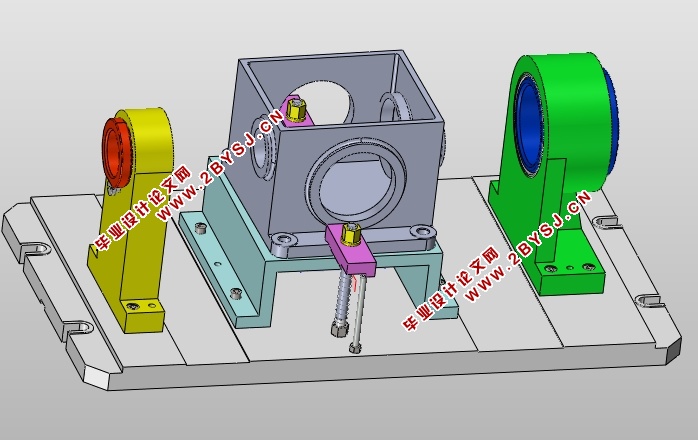
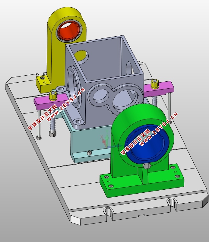
本文首先介绍了夹具的研究背景和被加工零件的材料、作用和一些特殊工序进行认真的分析,通过对参考文献进行对工时的计算,最后为了方便加工,以及保证加工精度,设计了镗φ100和φ60孔的夹具。
关键词:工艺编制,加工时间,专用夹具,生产率
Abstract
Through the analysis on the box are used for turbine reducer, gear reducer box body is made of cast iron sand mold casting forming, commonly cast iron than the tensile strength, plasticity and toughness of low carbon steel. Although the mechanical properties of cast iron is better than steel, but because of the existence of graphite is given by the many cast iron to steel is less than the performance. Such as good wear resistance, high damping resistance, low notch sensitivity, and good machinability. In addition, the carbon content of cast iron is high, its composition is close to the eutectic composition, thus the low melting point of cast iron, which is about 1200 ℃ or so, good hot metal flow, because the graphite crystal volume expansion, so send little shrinkage after machining to its processing to use requirement, in the process of production, the processing technology of the gear reducer box is very important to custom, design process of determines the precision of the gear reducer box and the production efficiency, especially in the mass production of reducer casing, the technical process to production into consideration. At the same time, in order to ensure the workpiece machining accuracy, and in order to improve the productivity and the development of each process of special fixture, the operator is to use a simple, rapid and accurate, and on the premise of guarantee accuracy greatly improved productivity.
This article first introduces the research background of fixture and processed materials and function of the parts, the earnest analysis, and some special process of reference for the calculation of working hours, and finally to facilitate the processing, and guarantee the machining accuracy, the design of 100 and phi phi 60 boring fixture.
Key words: machining process, machining time, special fixture, productivity
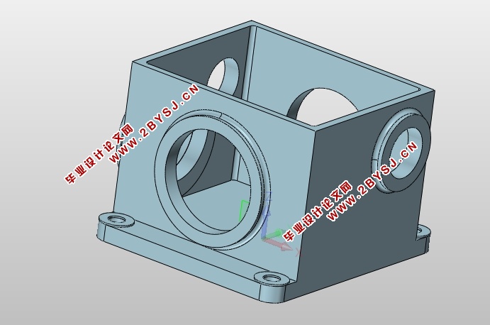
零件作用的分析
减速器箱体是减速器的重要组成部分。减速器是一种动力传达机构,利用齿轮的速度转换器,将马达的回转数减速到所要的回转数,并得到较大转矩的机构。 减速器的作用
(1)降速同时提高输出扭矩,扭矩输出比例按电机输出乘减速比,但要注意不能超出减速器额定扭矩。
(2)降速同时降低了负载的惯量,惯量的减少为减速比的平方。所以在日常的生活工作中运用得非常广泛,也起到非常重要的的作用。减速器箱体是减速器的外壳部分,在它里面存放齿轮轴、涡轮、蜗杆等核心零件,对齿轮和轴的正常运行有着支撑作用。
1.1.2 零件的工艺分析
减速器箱体一般采用铸铁砂型铸坯成型,铸铁的抗拉强度、塑性和韧性要比碳钢低。虽然铸铁的机械性能不如钢,但由于石墨的存在,却赋予铸铁许多为钢所不及的性能。如良好的耐磨性、高消振性、低缺口敏感性以及优良的切削加工性能。
铸造生产具有能够生产形状复杂的毛坯,特别是内腔形状复杂的毛坯;适应性广可节省金属材料和机械加工的工作量;生产成本较低的优点。但铸造生产存在着工序复杂,铸件容易产生缺陷,废品率较高,铸件的力学性能低于锻件,劳动条件较差等问题。
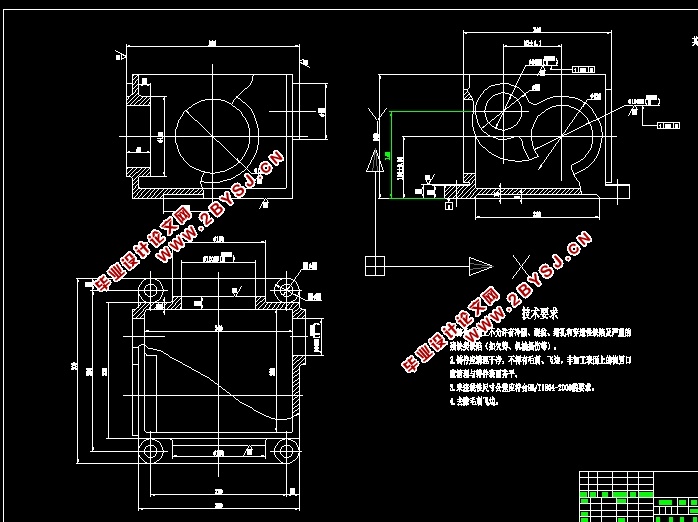
现在将箱体的工艺分析如下:
(1)以100±0.1下平面为主要加工表面的表面加工。包含铣100±0.1下平面,钻4-φ20孔。100±0.1下平面、4-φ20孔粗糙度为Ra3.2μm。
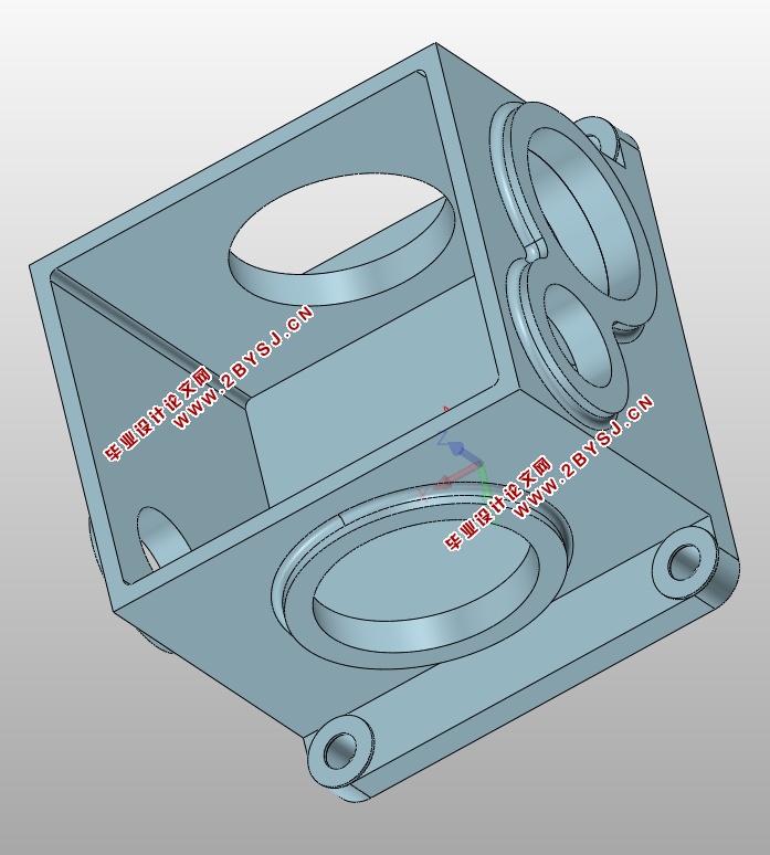
(2)尺寸端面的加工。包括尺寸端面的铣削加工;2-φ120H8孔的加工。尺寸端面、2-φ120H8孔的粗糙度值为Ra3.2μm。
(2)尺寸端面的加工。包括尺寸端面的铣削加工;2-φ60H8孔、φ100H8的加工。尺寸端面、2-φ60H8孔、φ100H8孔的粗糙度值为Ra3.2μm。
(4)以22上平面的加工。包括22上平面铣削加工。各加工面的粗糙度为Ra3.2μm。
1.2箱体加工的问题和工艺过程设计所应采取的相应措施
根据设计图纸可以看的出,2-φ60H8孔、φ100H8孔的中心线与100±0.1下平面要达到平行度0.04mm的精度

目 录
第一章 加工工艺规程设计 1
1.1 零件的分析 1
1.1.1 零件的作用 1
1.2 箱体加工的问题和工艺过程设计所应采取的相应措施 2
1.2.1 孔和平面的加工顺序 2
1.2.2 孔系加工方案选择 2
1.3 箱体加工定位基准的选择 2
1.3.1 粗基准的选择 2
1.3.2 精基准的选择 3
1.4 箱体加工主要工序安排 3
1.5 机械加工余量、工序尺寸及毛坯尺寸的确定 5
1.6确定切削用量及基本工时(机动时间) 5
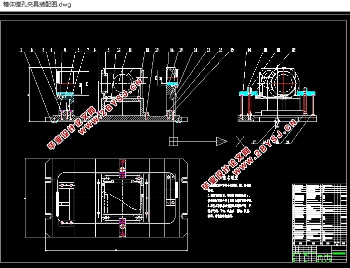
第二章 镗孔夹具设计 19
2.1定位基准的选择 19
2.2 镗削力计算 19
2.3定位元件的设计 20
2.4 定位误差分析 21
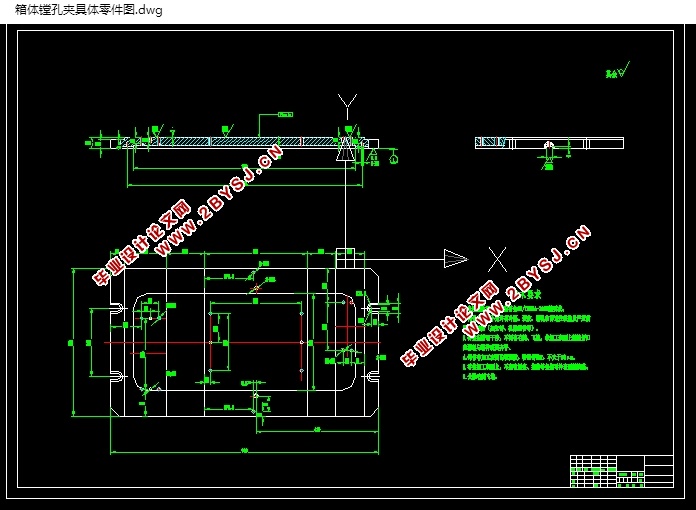
2.5 夹紧装置及夹具体设计 21
2.6 夹具设计及操作的简要说明 21
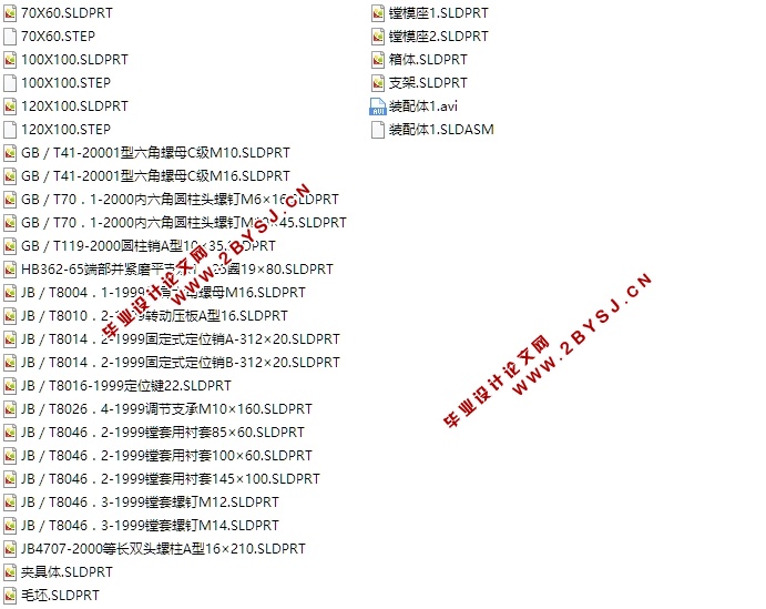
第3章 Solidworks建模并仿真 22
3.1 Solidworks介绍 22
3.2 Solidworks特点 22
3.3Solidworks建模 24
结 论 28
参考文献 29
致 谢 30