
轴瓦定位唇专用铣床夹具设计(含CAD零件图夹具图)
无需注册登录,支付后按照提示操作即可获取该资料.
轴瓦定位唇专用铣床夹具设计(含CAD零件图夹具图)(论文说明书17000字,外文翻译,CAD图纸3张)
摘 要
随着制造业对数控机床的大量需求以及计算机技术和现代设计技术的飞速进步,数控机床的应用范围还在不断扩大,并且不断发展以更适应生产加工的需要。在现有汽车发动机轴瓦定位唇加工中,所用的设备大多为普通铣床,。我国汽车轴瓦制造技术水平仍较低。其制造工艺发展缓慢,加工装备落后,加工自动化水平低,提高轴瓦寿命和可靠性等技术攻关未能取得突破。
本文在充分调研了国内外轴瓦定位唇专用铣床实际应用的前提下,深入了解和分析了国内外现有的技术特点和发展趋势。随着当今工业设备对精密程度的要求越来越高,机械加工设备的专项专用要求越来越高,且对批量生产和高速生产的需要,这已经越来越制约着当今机械工业的发展。越来越多的专用机械加工设备相继出现。而在中国的机械加工设备的铣床中普通车床没有对各种型号轴瓦铣削用的专业铣床。所以对铣床机型专业方面专用机床的设计和国产化是非常必要的。
关键词 轴瓦定位唇;铣床;结构设计。
Abstract
With surging demand of numerical control machine, and the rapid advance so as satisfy the needs of the production and processing. In the processing of the existing is still relatively low level. The slow development of manufacturing technology, processing equipment is backward, processing the low level of automation, improve bearing life and reliability technology research has failed to make a breakthrough.
Investigation of the subject in bearing bush positioning lip milling in home and abroad under the premise of understanding, analysis of the characteristics and the development tend of the technology, in this article. we present the overall design of the bearing efficiency. We are also based on finite element theory, the use of ANSYS, the dynamic analysis of the main shaft of bearing bush positioning lip milling was analyzed to verify the structural design is reasonalble and reliable.
Bearing bush positioning lip milling in this article is one of the few types of bearing bush positioning lip milling both domestic and overseas at present, it belongs to there are no special lathes which are used to produce bearing bush in China. Moreover, it is expensive to import the same type lathes and the maintenance charge is very high. It is vitally necessary to design and produce special purpose machines by ourselves.
Keywords positioning bearing bush lip, milling, structural design。
总体结构
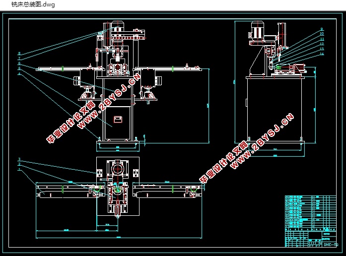
本课题轴瓦定位唇专用铣床与现有的普通铣床技术相比,由于整个加工都是全自动化的,各个环节减少了人工的劳动强度因而减少了因人的失误而造成的不必要的错误的发生,避免一些工伤等不安全因素的发生;其次,由于整个运行过程均是自动控制,这样可以在加工时使其对每个轴瓦的力量均衡,确保了加工每个轴瓦定位唇的稳定和精度,进而保证了加工出的定位唇的外形一致性,成品率也得到了提高[30]。由于本设备从送料到取料,均是自动控制,加工效率大大的提高了,另外采用立式铣的结构,不但可以避免加工屑的影响,而且减小了机身。轴瓦定位唇铣削专用铣床总体结构可以分为加工部分和进出料部分。由于加工装置的模具下端的弹簧稳定性比较差,且根据计算需要三根弹簧,不能保证弹簧精确的同步运动,因此改用气压缸夹紧工件的运动。
综合上述设计思想,本设计的轴瓦定位唇铣床的总体结构简图如图2-4所示。
1-机架;2-伺服电机;3-滚珠丝杠;4-取料机械手;5-取料输送带;6-滑台;7-送料机械手;8-送料输送带;9-下汽缸;10-支架;11-底座;12-调整机构;13-动力箱;
14-脱模机构;15-工作台


目录
摘 要 I
Abstract II
第1章 绪论 1
1.1 课题研究的背景 1
1.2 国内外研究现状 2
1.2.1 国外研究现状 2
1.2.2 国内研究现状 5
1.3 主要工作内容 6
第2章 轴瓦定位唇铣床结构设计 8
2.1 工艺流程 8
2.2 总体设计的基本要求 9
2.3 总体结构布局 10
2.3.1 总体结构布局原则 10
2.3.2 方案的拟定 10
2.3.3 基本构成 11
2.4 总体结构及工作原理 12
2.4.1 总体结构 12
2.4.2 工作原理 13
2.5 运动和动力分析 15
2.5.1 运动分析 15
2.5.2 动力分析 16
2.3.2电动机功率计算 17
第3章 主要结构设计 18
3.1.1 滚珠丝杠的设计方案 18
3.1.2 机械手的设计方案 18
3.1.3 动力箱的设计方案 19
3.1.4 本章小结 20
第4章 三维软件分析 21
4.1 Solidworks软件介绍 21
4.2铣削状态研究 24
4.3 适应轴瓦的加工范围 24
4.4铣床综合分析 25
致 谢 26
结 论 27
参考文献 29
附 录1 31
附 录2 34