
������ǰ������ʽר���۴����(��CAD���ͼ�о�ͼ)
����ע���¼,֧��������ʾ�������ɻ�ȡ������.
������ǰ������ʽר���۴����(��CAD���ͼ�о�ͼ)(������,����˵����15000��,���ķ���,CADͼֽ7��,���PPT)
ժ Ҫ
����Ƶ���Ŀ�DZ��������ר���۴���ƣ���ҪĿ����ͨ�������������ѧ��רҵ֪ʶ����ʵ������������Լ����������ͽ������������������ꡢ�����µĴ�ͳ���գ�����Ч�ʵͣ������ȶ��Բ���Ȳ����ױ�֤����Լ�������ķ�չ�����Ǿ����������һ̨��������ר�û�����
��ȫ���˽�ר���۴��Ľṹ������ԭ���Ļ����ϣ�����ѡ�ò�������Ƴ��۴��Ĵ���ϵͳ��ִ�л����������۴��Ĺ���ԭ����ȷ���˸��۴��Ľṹ�뼼�������������˸��۴��Ľṹ��Ʒ�����
������Ʒ��������Ľ�����ר���۴���������ơ��ṹ��ƺͼоߵ���ơ��оߵ�������۴��������Ҫ��һ���֣���˼о���Ƶĺû�����ֱ��Ӱ�챻�ӹ�����ľ��ȡ�����������ƵĻ����������ۿף��ڼӹ���������ͬʱ�ӹ�3���ף������ܴ���������Ч�ʣ������Ͷ�ǿ�ȣ��Ӷ�����������ļӹ��ɱ���
�ؼ��� ר���۴�����������壻�ṹ��ƣ��о����
Abstract
The topic of the paper is the structure design of special boring machine for shell of gearbox. The main purpose is to apply the professional knowledge to practice and improve the ability of analyzing and solving difficult problems. The traditional process which uses drill expands and articulation, not only gains the lower efficiency, moreover, its stability is bad and its precision is not easy to guarantee as well, so it restricted the production development. So we decide to design a high grade special purpose machine independently.
Based on the comprehensive understanding of the structure and working principle of the special boring machine, Reasonable selection of parts, Determine the boring machine's structure and technical parameters, given the structural design of the boring machine according to the working principle.
According to the design, this paper introduces a special boring machine's overall design, structural design, and fixture design. Fixture design is an important part of the boring machine design, Therefore the Fixture design is good or bad, Will directly affect the precision of machining parts. In the paper, the machine tool we designed is used for drilling hole, and it could process 3 holes in the production line simultaneously. So we enhance the production efficiency greatly, reduce the labor intensity, and reduce the components processing cost.
Key words The Special Boring Machine; Shell of Gearbox; Structure Design; Fixture Design
�����ӹ�Ҫ��
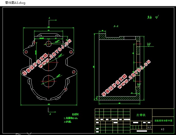
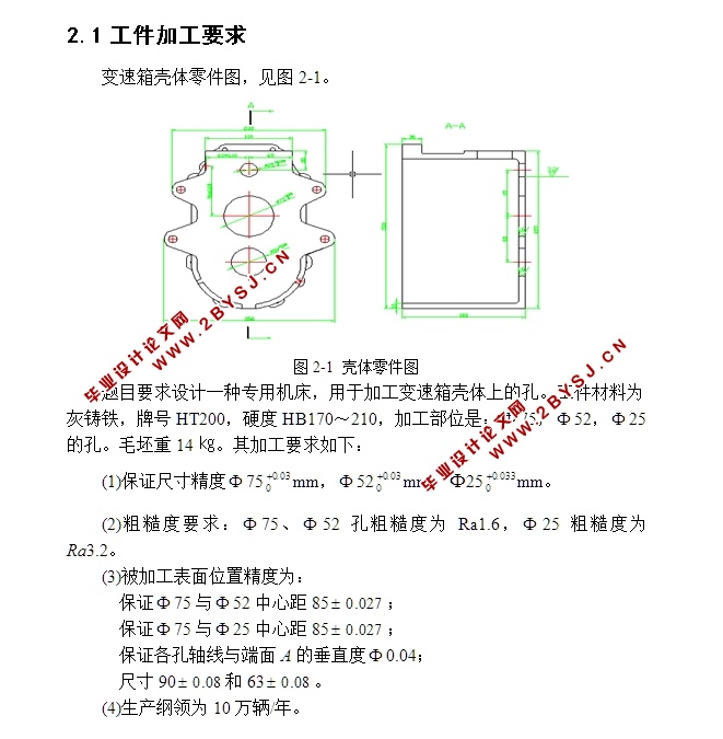
��ĿҪ�����һ��ר�û��������ڼӹ�����������ϵĿס���������Ϊ���������ƺ�HT200��Ӳ��HB170��210���ӹ���λ�ǣ� 75�� 52�� 25�Ŀס�ë����14�K����ӹ�Ҫ�����£�
(1)��֤�ߴ羫�� 75 mm�� 52 mm�� 25 mm��
(2)�ֲڶ�Ҫ�� 75�� 52�״ֲڶ�ΪRa1.6�� 25�ֲڶ�ΪRa3.2��
(3)���ӹ�����λ�þ���Ϊ��
��֤ 75�� 52���ľ�85 ��
��֤ 75�� 25���ľ�85 ��
��֤�������������A�Ĵ�ֱ�� 0.04��
�ߴ�90 ��63 ��
(4)��������Ϊ10����/�ꡣ
2.2 ���շ����ƶ�
��������ӹ�Ҫ���侫��Ҫ��ϸߣ����ݳߴ硢λ�þ��ȵ�Ҫ��ר�û����豸�����ı�7-13��������ͬ���ȿĵ����շ�������7-14��ϻ����ӹ����Ⱥͱ���ֲڶ����ݣ�ѡ�þ��ۼӹ�������
Ŀ ¼
ժҪ I
Abstract II
��1�� �� �� 1
1.1 ���ⱳ�� 1
1.2 �о�Ŀ�ļ����� 1
1.3 ��������ϻ�����չ���� 1
1.4 ��ϻ������� 4
1.5 ��Ƶ���Ҫ���ݡ�������Ԥ�ڳɹ� 6
��2�� ����ӹ��������� 7
2.1 �����ӹ�Ҫ�� 7
2.2 ���շ����ƶ� 7
2.3 ȷ������������ѡ�� 8
2.3.1 ȷ����������� 8
2.3.2 ѡ���������� 8
2.3.3 ѡ�߽ṹ 9
2.4 ȷ��������������Ť�ء��������� 9
2.5 ͨ�ò�����ѡ�� 11
2.6 ������ 12
��3�� ����������� 13
3.1 ���ӹ��������ͼ 13
3.2 �ӹ�ʾ��ͼ 13
3.3 ������ϵ�ߴ�ͼ 15
3.3.1 �о������ߴ��ȷ�� 16
3.3.2 ����װ�ϸ߶�H��ȷ�� 16
3.3.3 �м���������ߴ� 17
3.3.4 �����������ߴ� 17
3.4 ���������ʼ��㿨 18
��4�� ��������� 21
4.1 ��������Ƶ�ԭʼ����ͼ 21
4.2 �������ʽ��ֱ����ȷ�� 21
4.3 ����ϵͳ����� 22
4.3.1 �ⶨ����·�� 23
4.3.2 ����ϵͳ���� 23
4.4 ��άģ�� 25
4.5 ��������� 25
4.6 У�˴�����5�� 27
4.7 ����������� 30
4.8 ���ƶ�������ͼ�����ͼ 31
4.9 ������ 31
��5�� ���� 32
5.1 ����� 32
5.2 ����װ�� 32
5.3 �н�װ�� 33
5.4 ������ 33
���� 34
��л 35
����� 36
��¼1 37
��¼2 42