
动力齿轮齿条转向器的设计(含CAD零件装配图)
无需注册登录,支付后按照提示操作即可获取该资料.
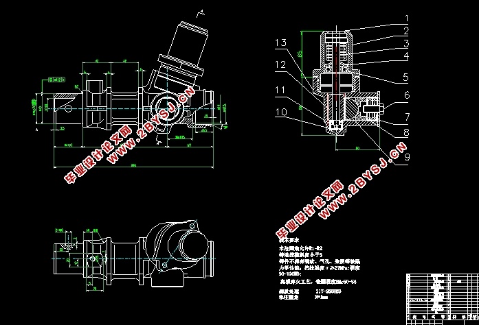
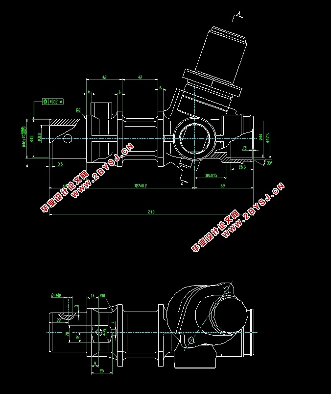
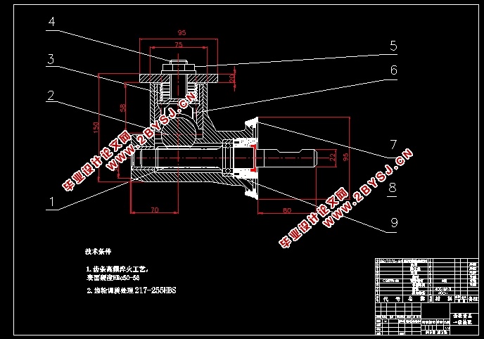
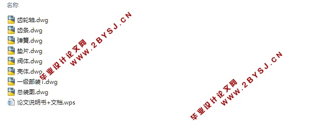
动力齿轮齿条转向器的设计(含CAD零件装配图)(任务书,开题报告,中期检查表,外文翻译,论文说明书13000字,CAD图8张)
摘要
随着经济的迅速增长,汽车工业得到了迅猛发展。作为汽车重要安全部件之一的转向系统也取得了跨越式发展。汽车转向器主要用于汽车驾驶过程中的转向操作,其性能的重要性不言而喻。本论文通过查阅国内外研究现状和现有机械转向器的类型特点,选用齿轮齿条作为汽车转向器的主体机构方案。首先在考虑转向器基本功能实现的前提下,以方向盘带动齿轮齿条转向轴,万向节带动转向齿轮轴,其后齿轮轴与齿条配合实现转向操作。通过计算校核设计的安全可靠性。最后,利用三维软件针对齿轮齿条转向机构进行三维建模,并验证该主体机构尺寸设计的合理性。
关键词:齿轮齿条设计;转向系统;转向器
Abstract
With the rapid economic growth, the automotive industry has been developing rapidly. As one of the important safety components of automobiles, the steering system has also made great stride development. Automobile steering gear is mainly used in steering operation during vehicle driving, and its importance is self-evident. Through consulting the research status at home and abroad and the characteristics of the existing mechanical steering gear, this paper selects rack and pinion as the main body mechanism of automobile steering gear. First, on the premise of realizing the basic function of the steering gear, the steering wheel drives the gear and rack steering axis with the steering wheel, the universal joint drives the steering gear shaft, and then the gear shaft is cooperated with the rack to realize the steering operation. The safety and reliability of the design is calculated. Finally, the 3D modeling of the rack and pinion steering mechanism is carried out by three-dimensional software, and the rationality of the size design of the main body is verified.
Keywords: Gear and rack design Steering system Steering gear
目录
摘要 I
Abstract II
第1章 绪论 1
1.1 概述 1
1.2 转向器的作用与分类 1
1.3 汽车转向装置的发展趋势 3
1.4 汽车转向器国内外现状 4
1.5 设计的主要内容 6
第2章 齿轮齿条转向器设计方案选择 7
2.1转向系主要性能参数 7
2.2 转向器总体方案设计 8
2.2.1 转向器设计方案说明 8
2.2.2 转向器输入输出形式 8
2.2.3 转向器输出形式对比分析 9
2.2.4 转向器齿轮齿条选择 9
2.2.5 转向器齿条断面形状选择 9
2.2.6 转向器的四种布置形式 10
2.2.7 转向器最终方案确定 11
2.2.8 本章小结 11
第3章 设计计算过程 12
3.1 侧偏角的计算 12
3.2 原地转向阻力矩的计算 13
3.3 力传动比与角传动比对比分析 13
3.3.1 两种传动比基础介绍 13
3.3.2 角传动比与力传动比确定 14
3.4 转向器齿轮齿条的设计 15
3.4.1 啮合传动的特点 15
3.4.2 齿轮参数的选择 16
3.4.3 接触疲劳许用应力 16
3.4.4 齿轮的齿根弯曲强度设计 17
3.4.5 齿轮主要参数选取计算 18
3.4.6 齿条主要参数选取计算 19
3.4.7 齿面接触疲劳强度校核 20
3.4.8 本章总结 20
第4章 齿轮轴的设计 21
4.1 传动受力分析 21
4.2 最小轴径确定 21
4.3 强度校核 21
4.3.1 本章小结 24
第5章 间隙调整弹簧的设计 25
5.1 弹簧材料 25
5.2 计算弹簧丝直径 25
5.3 弹簧圈数和自由高度的计算 26
5.4 校核与内外径的确定 26
5.5 工作时的数据 27
5.5.1 本章小结 27
第6章 轴承选择与润滑方式分析 29
6.1 轴承的选用方案 29
6.2 转向器润滑方式 29
6.2.1 本章小结 30
结论 31
参考文献 32
致 谢 33
附录A 外文翻译 34