
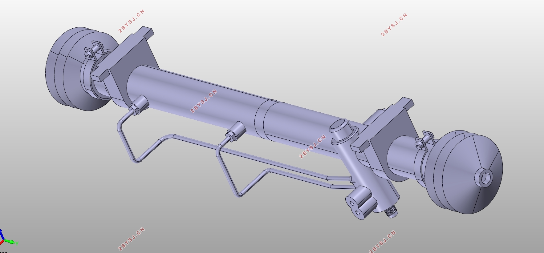
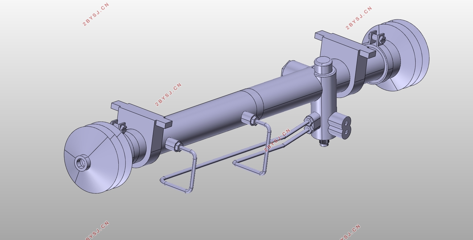
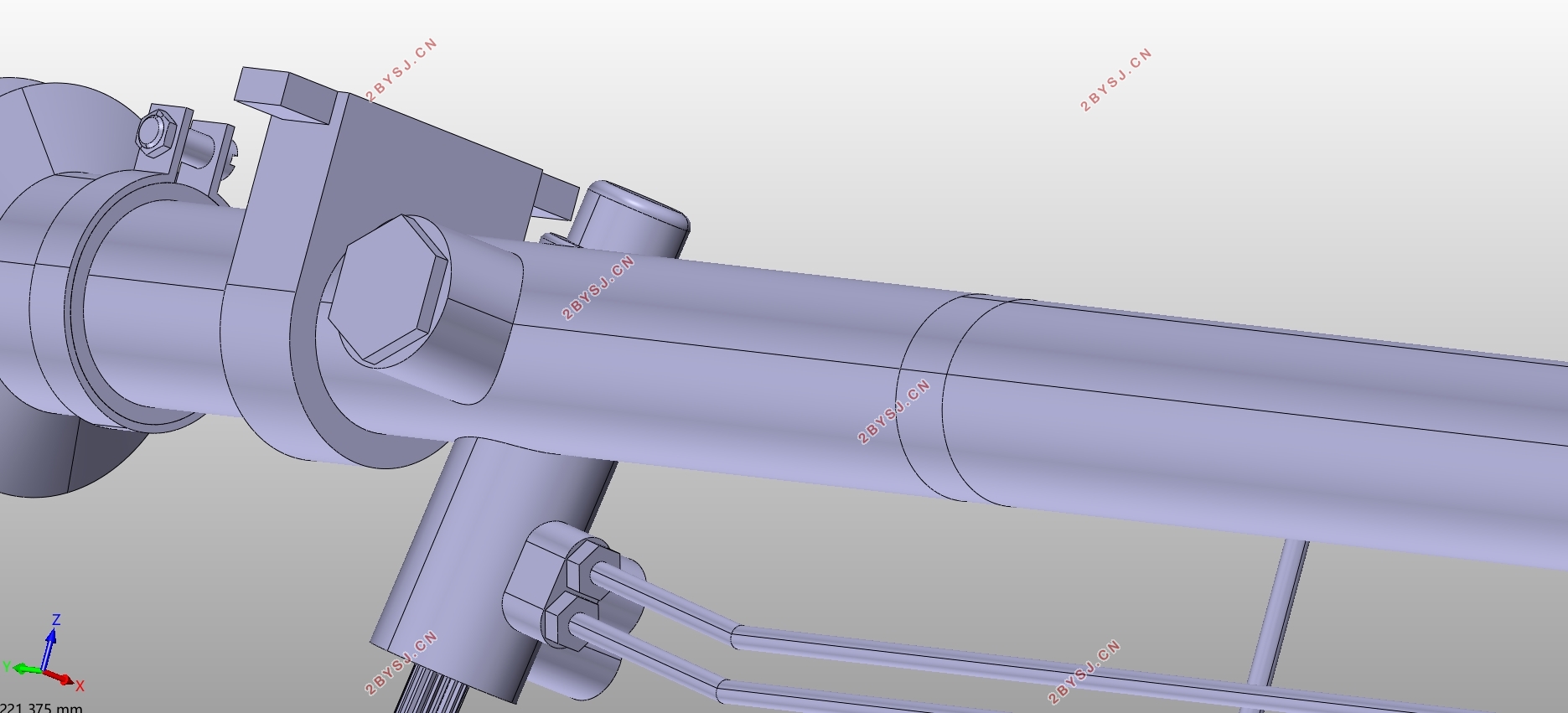
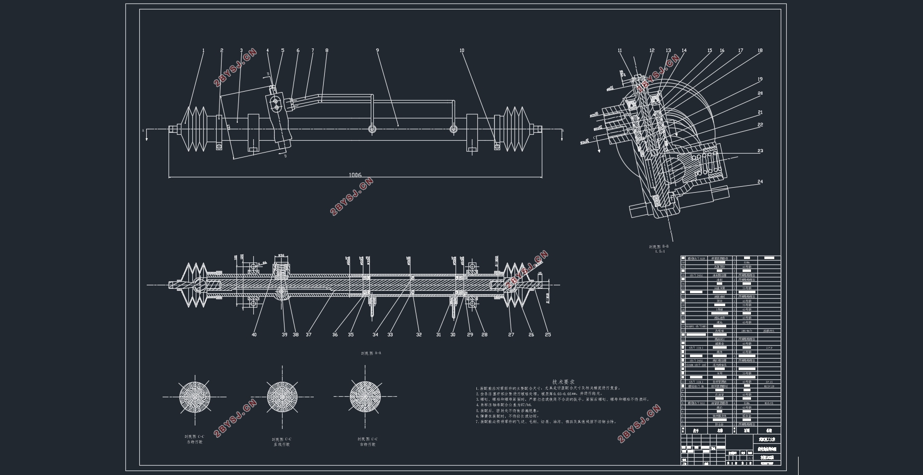
齿轮齿条式转向器设计(含CAD零件图装配图,CATIA三维图)
无需注册登录,支付后按照提示操作即可获取该资料.
齿轮齿条式转向器设计(含CAD零件图装配图,CATIA三维图)(任务书,开题报告,论文说明书15000字,CAD图纸8张,CATIA三维图)
摘要
此次毕业设计是对丰田的一款SUV进行齿轮齿条转向器的设计。我首先对曾在专业课上学的齿轮齿条式转向器的相关知识进行复习,了解它的大致结构和工作原理之后再去图书馆对相关资料进行查阅。通过对齿轮齿条转向器进一步的研究,我知道了不同类型齿轮齿条式转向器的优缺点以及不同类型齿轮齿条式转向器在现代汽车上的应用状况。接着根据车辆数据首先确定转向器的计算载荷以及转向器的主要参数,之后是确定齿轮齿条转向器的总体方案,然后确定齿轮齿条的形式以及它们的相关参数,在以上的设计基础上选择齿轮和齿条的材料,并且进行受力分析来对齿轮齿条安全强度进行校核。之后根据校核结果修正齿轮齿条式转向器中不合理的参数。最后通过对齿轮齿条式转向器的设计参数,选取出合适的标准零件如:螺钉和轴承等。
关键词:齿轮齿条;转向器;参数设计
Abstract
The graduation design is a Toyota SUV rack and pinion steering gear design. I would like to review the relevant knowledge of the gear rack-type steering gear in major courses, understand its general structure and working principle, and then go to the library to access the relevant information. Through the further study of the rack and pinion steering gear, I know the advantages and disadvantages of different types of rack and pinion steering gear and the application of different types of rack and pinion steering gear in modern cars.Then, according to the vehicle data, the calculated load of the diverter and the main parameters of the diverter are determined. Then, the overall scheme of the rack and pinion steering gear is determined.And the form of the rack and the rack and their related parameters are also determined. On the basis of the design, Gears and racks, and force analysis to verify the safety of the rack and pinion. And then correct the irregular parameters of the rack and pinion steering gear according to the checking result. Finally, through the rack and pinion steering gear design parameters, select the appropriate standard parts such as: screws and bearings.
Key Words:gear and rack;steering gear;parameter design
齿轮齿条转向器设计方案
2.1选取车辆的整体数据
丰田2012款RAV4车辆数据
驱动方式 前置四驱
整备质量 1620kg
发动机最大扭矩 224N•m/4000rpm
发动机功率 125Kw/6000rpm
轴距 2660mm
转向节臂长 180mm
轮距 1440mm
轮胎规格 225/65R17
主销偏移距 90mm
轮胎压力 0.22MPa
方向盘直径 400mm

目录
摘要 I
Abstract II
第1章绪论 1
1.1 引言 1
1.2 转向器的功能及分类 1
1.3 汽车转向器的发展趋势 2
1.4 转向器的国内外现状分析 3
1.5 设计主要内容 5
第2章齿轮齿条转向器设计方案 6
2.1 选取车辆的整体数据 6
2.2 齿轮齿条转向器总体方案设计 6
2.2.1 总体方案设计说明 6
2.2.2 齿轮齿条转向器的整车布置 6
2.2.3 齿轮齿条式转向器的输出形式 7
第3章转向系参数确定 9
3.1 转向系计算载荷确定 9
3.2 转向轮侧偏角的计算 9
3.3 转向器传动比的计算 10
第4章齿轮齿条的设计计算 12
4.1 齿轮齿条形式选择与啮合分析 12
4.2 斜齿圆柱齿轮与直齿齿条的参数设计 12
4.2.1 斜齿圆柱齿轮的参数设计 13
4.2.2 直齿齿条的参数设计 14
4.3 斜齿圆柱齿轮与直齿齿条的疲劳强度校核 15
第5章齿轮齿条转向器液压设计 18
5.1 液压系统形式的选择 18
5.2 液压系统参数设计 19
5.2.1 计算缸径Dc 19
5.2.2 活塞的设计计算 20
5.2.3 活塞行程的设计 20
5.2.4 动力缸壳体壁厚t的设计计算 20
5.2.5 活塞杆的设计 21
第6章调整弹簧的参数选择 23
6.1 调整弹簧的材料选择 23
6.2 调整弹簧的钢丝参数选择 23
6.3 调整弹簧的参数选择 24
6.4 调整弹簧工作时的参数 24
6.5 调整弹簧的参数校核 25
第7章转向器其他零件的选择与润滑方式的确定 26
7.1 轴承的选择 26
7.2 键的选择与校核 26
7.3 齿轮齿条转向器的润滑方式选择 27
第8章齿轮齿条转向器传动副的ANSYS分析 28
8.1 齿轮的ANSYS分析 28
8.2 齿条的ANSYS分析 30
结论 31
参考文献 32
致谢 34