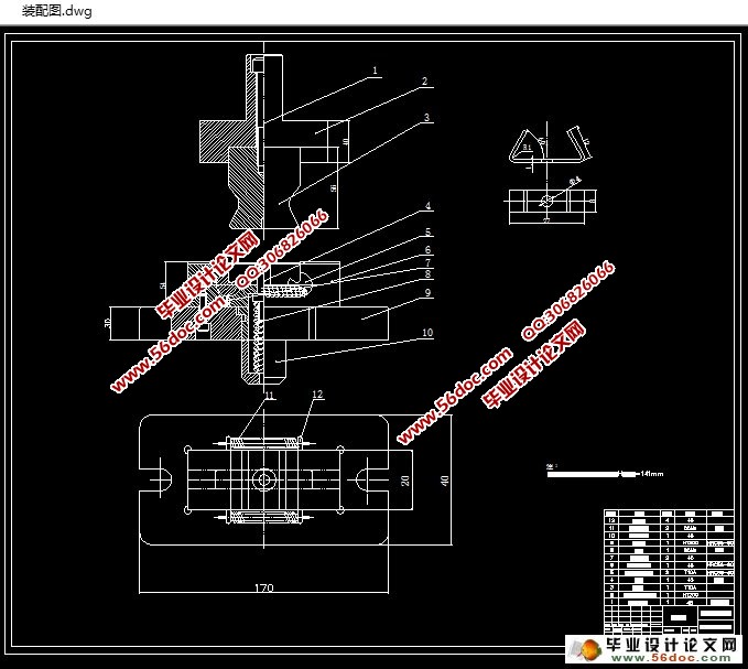
夹形件弯曲模设计(含CAD零件图装配图)
无需注册登录,支付后按照提示操作即可获取该资料.
夹形件弯曲模设计(含CAD零件图装配图)(文献综述,设计说明书13700字,CAD图6张,实习报告)
摘 要
在本设计说明书中包含两个比较可执行的方案,方案一是分多个工序来完成的弯曲模,方案二是一个单工序即可完成的弯曲模。为体现冲压工艺成型已成为现代工业生产工艺手段,关键还要显出了弯曲模的优势以及特色,并且要考虑到工件必须符合大批量生产工作,所以我选择设计方案二方案一个单工序的弯曲模具,该幅玩去模具在一次工作状态利用所设计的转轴式回转来完成弯曲成型。该幅模具设计结合了冲压和弯曲一次工作成型的效果,所以一般采取此类型用于工件弯曲角度较小的零件中。
本设计中的这个弯曲模在凹模座设计有一组转轴式回转凹模,内含在凹模座里面。凹模是一组左右相互对称且会活动回转转动的。凹模式一组组合式的转轴,关键还是内含在凹模的镶块之间,在制造生产该凹模也非常方便,只需要镶在凹模座里即可,拆卸维修也相对方便。
工作过程是这样的,当本弯曲模的凸模受力往下工作时,第一时间是把毛坯料件弯曲成角度为90°的U形件为先,跟着凸模接着受力下工作时,接着毛坯料件在凹模最低处随着转轴式凹模往里转,这样就成型出的效果是再次让毛坯料件弯曲来达到工件形状。完成成型后凸模接着受力上升,这样迫使转轴式凹模往外回转,这样使得限位钉的位置以及转轴式凹模上的弹簧回复原始状态。在本设计的转轴式回转凹模的弯曲模中,可以在一次工作状态下完成冲压和弯曲多步工序工艺,相对而言本设计的模具制造工艺不仅仅简单,而且制造成本也便宜。加上结构简洁。因此在现实工作生产中运用广泛。
在涉及到模具设计的进程中,先照着工件所需要的弯曲材料以及索要达到的工件厚度要求等等,深入计算出本设计中弯曲模具的毛坯料所需尺寸、在弯曲成型中所用的弯曲力大小、在弯曲中各种原因产生的回弹角度和本设计的弯曲模的凸模和凹模之间的间隙值的计算,并且寻找到比较恰当还符合本弯曲模具的定位以及卸料等要求。规划弯曲模的凸、凹模的外形的设计,敲定该幅模具要用的刚材料并规划设计种种零部件的设计加工工艺方案。接着整合该弯曲模具需要的总装配准则要求,接着即可完成该模具的总装配。装配已经再次修改调整的设计模具,把其模具设置在压力设备上对其设置调试,对其毛坯料试冲弯曲模。在此试模期间工作生产工件有暴露出生产出工件的缺陷时,应该对其暴露出的问题进行跟踪寻找并且找到应对解决方案,来不断完善生产出能达到合格率的工件产品。
关键词:冲压工艺,弯曲成型工艺,转轴式回转凹模
Abstract
In this paper, the design of two programs, the program is a multi process bending die, the program two is a single bending die. To reflect the stamping forming process has become a modern industrial production process means, but also to highlighting the characteristics of bending die, also need to consider to the workpiece to mass production, so the selection of the bending die for the second single process of scheme, it is forming a rotating shaft rotary bending die. The combined single working procedure is used for forming a movable concave die for a U shaped workpiece which is less than 90 degrees in the bending angle of the workpiece.
The bending die has a pair of rotating shaft type concave modules corresponding to the notch, and the notch and the relative deserve are the shape of the work piece. The concave die is the left and right symmetry and the activity turns. The rotary shaft of a group of combined type is concave, and is embedded in the concave mold insert block, which is convenient for mechanical processing.
When the bending die punch followed press slide under pressure. First of all, the blank in the die bent into 90 degrees of the U shaped parts, with the punch to press the blank bottom pressure rotary die and concave die in rotation by pressure rotating the roughcast again bending is complete. When the convex die is picked up with the slide block of the press, the rotation of the rotating shaft of the rotating shaft is rotated, and the spring on the limit pin and the rotating shaft is made to restore the initial position of the rotary die. Because the rotating shaft type rotary bending concave die can be in the press of a decline and rise in the completion of a few pairs of single process die in order to complete the bending process, and the mold process is simple, simple structure. Therefore, the use of more in the actual production.
Into the mold design process, according to the workpiece material and the thickness of the workpiece and workpiece properties, design analysis calculation of the bending die Mao Piliao, bending, springback angle and the convex and concave die clearance etc.; find out the proper positioning of the bending die and ways of loading and unloading. The working part of the mold design calculation is divided into convex and concave die design, select the material used in the mold and determine the processing technology of each component. According to the general assembly rules of the mold, the total assembly of the mold is completed. Fit the mold, installation to the machine equipment for debugging and testing. If it is found that does not meet the requirements of the need to be amended, and again to debug the test mode, until the normal operation and processing of qualified parts.
Keywords: Stamping process, bending forming process, rotating shaft rotary die


目 录
摘 要 I
1 弯曲工艺性分析 1
1.1 工件成型构造图并设计冲压弯曲方案 1
1.2 分析工件的弯曲结构工艺性 2
1.3 最小相对弯曲半径的确定 3
2 工件的结构工艺性分析 5
2.1 工件在弯曲成型的最小弯曲半径 5
2.2 工件在弯曲成型的形状与尺寸的对称性 5
3 工件弯曲成型的工序安排 7
3.1 工件在弯曲成型时的工序安排原则 7
3.2 弯曲件的工序安排 7
4 需改进工件的结构设计 9
4.1 工件的材料的热处理 9
4.2 对模具结构采取措施 9
4.3设计弯曲模结构注意事项 9
5 工件弯曲成型工艺的计算 11
5.1 自由弯曲时弯曲力的分析 11
5.2 校正工件在弯曲时的弯曲力 11
5.3 顶件力和压料力估算 12
5.4 选择压力机吨位 12
6 毛坯展开尺寸及回弹量的计算 13
6.1 毛坯弯曲尺寸见图 13
6.2 毛坯的展开尺寸计算 13
6.3 回弹量的计算 14
6.4减少回弹在弯曲成型中的办法 15
7 设计确定该工件弯曲模主要工作零件结构参数 17
7.1 确定凸模与凹模的圆角半径参数 17
7.2 凹模工作部分深度 17
7.3 弯曲凹、凸模的间隙 18
7.4 凸、凹模横向尺寸及公差 19
8 模具总体设计 21
8.1 模具的凸、凹模部件的设计 21
8.2 弯曲设备的选择 23
8.3 设备的确定 24
8.4 绘制模具装配图 25
8.5 该模具非标准零件图 26
9 模具定位方式和卸料、出料装置的概述 27
9.1 模具类型的选择准则 27
9.2 定位方式的确定 27
9.3 卸料方式和出件装置简述 27
10 模具材料的选用以及其他零部件的设计 29
10.1 模具材料的选用 29
10.2 模具零件加工工艺 30
11 模具的装配和模具冲裁的试模 33
11.1 模具的装配 33
11.2 模具的调试 34
致 谢 36
参考文献 37
