外环落料,冲孔,翻边,复合模具设计(含CAD零件图装配图)
无需注册登录,支付后按照提示操作即可获取该资料.
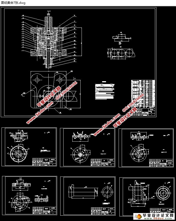
外环落料,冲孔,翻边,复合模具设计(含CAD零件图装配图)(文献综述,设计说明书10000字,CAD图7张)
摘 要
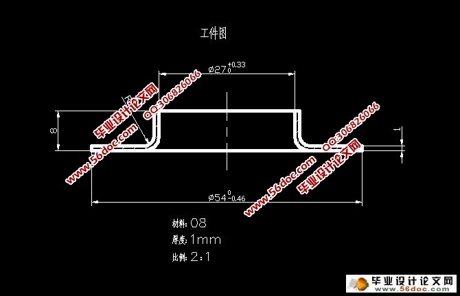
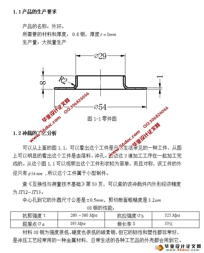
本次毕业设计为外环的模具设计,该工件是由落料、冲孔、翻边这几套工序在一副复合模加工完成的,虽然模具的总体结构较为复杂,但是做出的工件的精度和生产效率都很高,操作相对来也更方便、安全性也高。该工件是在压力机上一次完成的这几道加工工序。这个设计运用的知识面较广泛的,比如《模具设计大典》、《冲工艺与模具设计》、《CAD/CAM》等,这些专业知识都在本设计要用的。
本次论文主要对复合模的整体工艺分析,冲裁力、主要工作尺寸的计算;还介绍了落料凹模、冲孔凸模等主要零部件的设计和选择等。
关键词:冲孔;翻边;复合模
ABSTRACT
The graduation design for the outer ring of the mold design, the workpiece is by blanking, punching and flanging of the several sets of process in a pair of compound die processing completed, although the overall structure of the mold is more complex, but make the workpiece precision and the production efficiency is high, operation is relatively more convenient, high safety. The workpiece is in the press a completed this process. This design uses a wider knowledge, such as < Mold Design Canon >, < rushed process and design of die for >. <CAD/CAM>. These professional knowledge are in this design to use.
In this paper, the overall process analysis of the compound die, punching force, the calculation of the main working dimensions; also introduces the blanking die, punching punch and other main parts of the design and selection.
Key words:Punching flanging compound die;


目 录
摘 要 1
ABSTRACT 2
目 录 3
绪 论 1
1.工件冲压工艺性分析和确定方案 3
1.1产品的生产要求 3
1.2冲裁的工艺分析 3
1.2.1翻边的工艺性 4
1.2.2是否能一次性翻边成形 4
1.3 确定工艺方案 5
2.工件的工艺计算 6
2.1排样及计算材料利用率 6
2.1.1预冲孔大小的计算 6
2.1.2排样方式的确定 6
2.1.2计算材料利用率 7
2.2、冲压力的计算 8
2.2.1.落料力: 8
2.2.2卸料力 9
2.2.3冲孔力 9
2.2.4顶件力 9
2.2.5翻边力 9
2.2.6总冲压力 10
2.2.7计算压力中心 10
2.3模具刃口尺寸计算 10
2.3.1落料刃口的尺寸 11
2.3.2冲孔刃口的尺寸 11
2.3.3翻边刃口的尺寸 12
2.4凸模、凹模和凹凸模的设计与校核 12
2.4.1设计落料凹模结构 12
2.4.2凹模外形尺寸的确定 13
2.4.4落料、翻边凸凹模外形尺寸计算 14
2.4.5冲孔、翻边凸凹模外形尺寸计算 16
2.4.6冲孔凸模外形尺寸计算 17
3.部分零部件设计 20
3.1模柄的设计 20
3.2固定板和垫板的设计 21
3.2.1冲孔、翻边凸凹模固定板的设计 21
3.2.2冲孔凸模固定板的设计 22
3.2.3垫板的设计 22
3.3定位零件的设计 23
3.3.1定位销的设计 23
3.3.2圆柱销的设计 24
3.4出件机构的设计 25
1.推板 25
2. 推杆 25
3.上顶杆 26
4.上顶板 26
3.4.2下出件机构的设计 27
1.下顶杆 27
2.圆柱螺旋压缩弹簧 27
3.下顶板 28
4. 模架与压力机的选择 29
4.1模架的选择 29
4.1.1模具的闭合高度计算 29
4.2压力机的选择 29
5. 模具总装图 31
5.1下图就是模具装配图: 31
总 结 33
致 谢 34
参考文献 35
