基于TDA2822双声道音频功率放大器设计
无需注册登录,支付后按照提示操作即可获取该资料.
基于TDA2822双声道音频功率放大器设计(论文13000字)
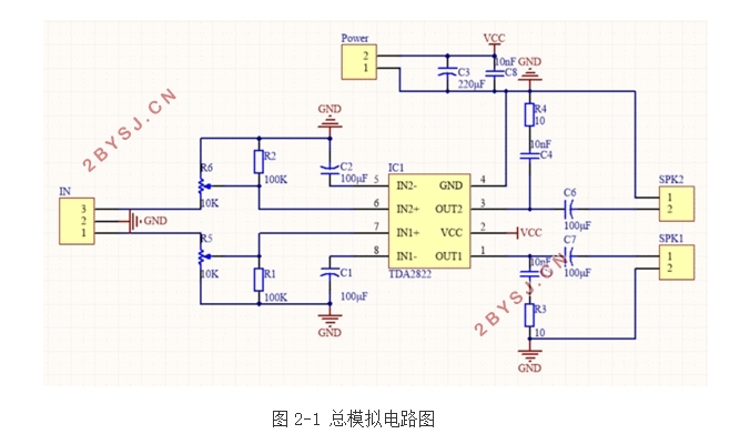
摘要:近些年来,随着电子工业技术和电子电工产业的发展,制造电子元器件的能力已经越来越重要。由于生产技术的提高和加工工艺的改进,因此集成电路技术的发展也很快。在此研究背景下,本论文运用了Altium Designer模拟仿真电路系统设计制作了一个基于TDA2822集成电路的双声道音频功率放大器,研究目标是以电压放大倍数为参数标准实现对双声道音频信号功率的放大。此电路成本低,音质好,电压范围宽,简洁明了。本设计既可以应用于家用迷你音箱,也可以制作成商用音响系统,也可以作为实验教学,用途广泛。
关键字:TDA2822;功放及制作;电子工艺
Dual Channel Audio Power Amplifier Based on TDA2822
Abstract:In recent years, with the development of electronics industry technology and electronic and electrical industries, the ability to manufacture electronic components has become more and more important. Due to the improvement of production technology and the improvement of processing technology, the development of integrated circuit technology is also fast. Under the background of this research, this dissertation uses Altium Designer analog simulation circuit system to design a dual-channel audio power amplifier based on TDA2822 integrated circuit. The research goal is to realize the power of two-channel audio signal with the voltage amplification factor as the parameter standard. Zoom in. This circuit has low cost, good sound quality, wide voltage range, and simple and clear. This design can be applied not only to home mini speakers, but also to commercial sound systems. It can also be used as experimental teaching and has a wide range of applications.
Key words:TDA2822;power amplifier and production;electronic process

目 录
1 绪论…………………………………………………………………1
1.1 研究背景………………………………………………………………………………1
1.1.1 音频功率放大器的研究历史…………………………………………………1
1.1.2 集成电路的特点介绍及其应用………………………………………………1
1.1.3 音响电路的概念………………………………………………………………1
1.1.4 功率放大器的作用……………………………………………………………2
1.2 国内外研究现状………………………………………………………………………3
1.3 论文主要工作内容……………………………………………………………………4
1.4 论文组织结构…………………………………………………………………………4
1.5 本章小结………………………………………………………………………………4
2 电路设计方案框图…………………………………………………4
2.1 集成电路介绍…………………………………………………………………………4
2.1.1 集成电路的基本参数…………………………………………………………5
2.1.2 集成电路的工作原理…………………………………………………………5
2.2 Altium Designer介绍及仿真模拟电路图…………………………………………5
2.2.1 输入回路………………………………………………………………………6
2.2.2 输出回路………………………………………………………………………6
2.2.3 电源电路………………………………………………………………………7
2.2.4 接地电路………………………………………………………………………7
2.3 集成电路各引脚及其外电路作用……………………………………………………8
2.4 直流和交流信号的传输过程和放大电路……………………………………………8
2.4.1 信号传输过程…………………………………………………………………8
2.4.2 放大电路分析…………………………………………………………………9
2.5 直流电源介绍…………………………………………………………………………9
2.6 本章小结………………………………………………………………………………10
3实现焊接电路………………………………………………………10
3.1 实验所用元器件………………………………………………………………………10
3.2 焊接好的实物图及整个电路工作实物图……………………………………………10
3.3 焊接总结………………………………………………………………………………11
3.4 本章小结………………………………………………………………………………12
4功能测试……………………………………………………………12
4.1调试准备工作…………………………………………………………………………12
4.2 电路调试………………………………………………………………………………12
4.3 故障排除………………………………………………………………………………13
4.4 调试结果………………………………………………………………………………13
4.5 定量分析………………………………………………………………………………14
4.6 本章小结………………………………………………………………………………16
5 总结与展望…………………………………………………………16
5,1 总结……………………………………………………………………………………16
5.2 展望……………………………………………………………………………………16
参考文献………………………………………………………………16
致谢……………………………………………………………………18
