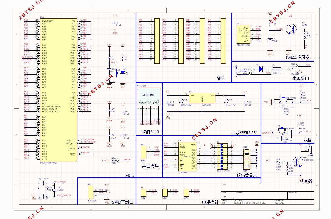
基于STM32的空气质量检测仪(含原理图,程序,答辩记录)
无需注册登录,支付后按照提示操作即可获取该资料.
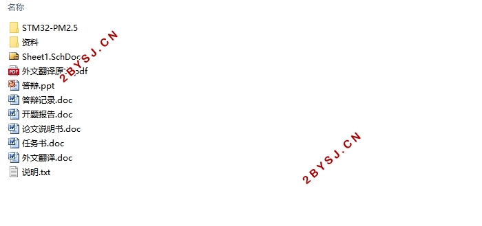
基于STM32的空气质量检测仪(含原理图,程序,答辩记录)(任务书,开题报告,外文翻译,论文说明书12000字,原理图,程序代码,答辩PPT,答辩记录)
摘要
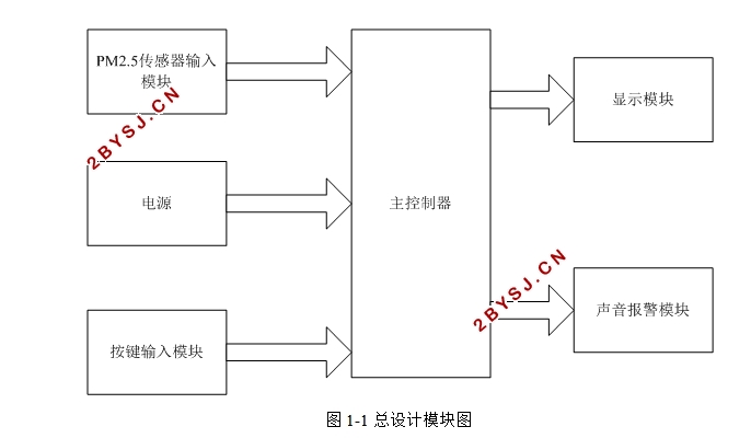
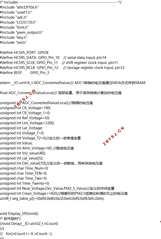
随着全球现代化水平的加速迈进,环境污染日益加重,尤其是空气质量状况受到越来越多的关注。本文研究的PM2.5空气质量检测仪以ST公司STM32F103微控制器为核心,利用夏普公司的GP2Y1010粉尘传感器,可对当前空气中PM2.5浓度的实时探测,并将测量结果以数字形式在液晶屏上显示。同时,当所测得浓度值超过预设警告值时,系统可以蜂鸣的形式提示用户。系统采用IAR EWARM 6.3及ST公司STM32固件函数库3.5版本开发。测试结果表明,本系统达到了预期效果,基本符合设计要求。
本文第一章首先对本课题的目的及本课题的研究现状进行简要阐述和对本次研究的主要内容、设计方法以及主要难点进行讨论。第二章对各个模块的实现方法和具体电路进行了分析,对设计中用到的主要集成芯片进行了介绍。第三、四章具体阐述了硬件及软件的具体设计与实现过程。最后系统的整体调试与小结。
关键词:STM32PM2.5测量显示报警
STM32 Based Air Quality Detector
Abstract
With the acceleration of global level towards modernization, environmental pollution is increasing, especially air quality conditions are more and more attention. In this paper, the PM2.5 air quality testing instrument companies in ST STM32F103 microcontroller core, the use of Sharp's GP2Y1010 dust sensor, real-time detection of the current concentration of PM2.5 in the air, and the measurement results in digital form using a liquid crystal screen display. Meanwhile, when the measured concentration exceeds a preset alarm value, the system can prompt the user in the form of beeps. The system uses IAR EWARM 6.3 and ST's STM32 firmware library version 3.5 development. The test results show that the system has reached the desired results, in line with the design requirements.
This article first chapter on the purpose and status of research of this subject this subject briefly described and the main content of this research, design methods, and the main difficulty for discussion. The second chapter of the methods and specific circuit of each module is analyzed, the design used in the major integrated chip were introduced. The third and fourth chapters specifically addressed the specific design and implementation of hardware and software.
Key Words :STM32;PM2.5 Detected;WarningDisplay


目 录
摘要 I
ABSTRACT II
第一章绪论 1
1.1 设计目的和意义 1
1.2 目前相关技术的发展情况 1
1.3 关于本课题的重点、难点讨论 1
第二章总体方案 4
2.1系统框图 4
2.2单片机模块 5
2.2.1 单片机的选择与介绍 5
2.2.2 USART串口 7
2.3 传感器模块 9
2.3.1 传感器的选型 9
2.4 显示、声音和输入模块 11
2.4.1 显示模块 11
2.4.2 声音模块 11
2.4.3 输入模块 11
2.5系统总结 11
第三章硬件设计 13
3.1 传感器的硬件设计 13
3.1.1 传感器的工作原理 13
3.1.2 GP2Y1010AU0F传感器 13
3.1.3 传感器的接口 15
3.2 显示屏的硬件设计 16
3.2.1 2.8寸TFT显示屏简介 16
3.2.2 显示屏的接口 16
3.3 声音模块的硬件设计 17
3.3.1 蜂鸣器的简介 17
3.3.2 蜂鸣器的接口 17
3.4 按键输入模块的硬件设计 17
3.5 本章小结 17
第四章软件设计 19
4.1 系统开发平台 19
4.2 软件模块 20
4.2.1 系统流程 20
4.2.3传感器数据采集模块 21
4.2.4 屏幕显示模块 24
4.2.5 声音警告模块 24
4.2.6 用户输入模块 25
4.3 小结 26
第五章仿真调试 27
5.1 系统硬件调试 27
5.2 系统软件调试 28
5.3 本章小结 30
第六章结语 31
参考文献 32
致谢 33
