基于FPGA的多功能串行通信测试系统设计
无需注册登录,支付后按照提示操作即可获取该资料.
基于FPGA的多功能串行通信测试系统设计(任务书,开题报告,外文翻译,论文12800字)
摘 要
本文主要研究的就是基于FPGA的RS-232串口异步通信,通过Verilog HDL语言在FPGA芯片上设计实现各种总线控制器的功能。其中包括RS232控制器软件编程,USB串行数据的收发,最后实现USB与RS232互相通信的程序。
首先了解硬件构成以及MAX232芯片和CH376芯片电路的连接,学习并掌握Verilog语言编程。其次参考相关文献了解总线控制器,在Quartus11.0开发环境中,在FPGA芯片上设计实现各种总线控制器的功能。最后,利用signal tap嵌入式逻辑分析仪,检查各输出波形,以验证程序的正确性。
关键词:串口 USB总线 现场可编程门阵列
Multi-functional serial communication test system design based on FPGA
Abstract
This paper studying the RS-232 serial interface is FPGA-based asynchronous communication through Verilog HDL language design on FPGA chip functions of the various bus controller. Including RS232 controller software programming, USB serial data transceiver, the final realization of the program to communicate with each other USB RS232.
Firstly, understanding the composition and MAX232 chip connections and CH376 chip circuit hardware, learning and master the Verilog language. Secondly, referring to the relevant literature to understand the bus controller in Quartus11.0 development environment, designed and implemented in the FPGA chip functions of the various bus controller. Finally, the signal tap embedded logic analyzer, checking the output waveform, to verify the correctness of the program.
Key Words: Serial; USB bus; FPGA


目 录
摘 要 I
Abstract II
第一章 绪论 5
1.1 课题背景 5
1.2 FPGA现场可编程门阵列 6
1.3 Verilog HDL简介 7
第二章 常用串口总线分析 10
2.1 RS232 、RS422和RS485总线原理分析 10
2.1.1原理概述 10
2.1.2 MAX232芯片 12
2.1.3 串口通信接口组成 13
2.2 USB总线原理分析 15
2.2.1 USB总线简介 15
2.2.2 USB的硬件结构 15
2.2.3 USB硬件接口类型 16
2.2.4 数据传输模式 17
2.2.5数据包格式 18
2.2.6 CH376芯片 19
第三章 系统硬件设计 20
3.1 系统整体设计 20
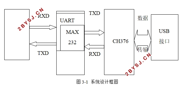
3.1.1 系统设计框图 20
3.2 UART设计原理 20
3.2.1 UART原理框图 20
3.2.2 UART设计电路图 22
3.3 USB设计原理 23
3.3.1 USB原理框图 23
3.3.2 USB数据读取电路图 24
第四章 系统软件设计 25
4.1 软件系统整体设计 25
4.1.1 功能简述 25
4.2 USB控制部分 25
4.2.1 USB控制 25
4.2.2 常用命令说明 26
4.2.3 USB控制部分功能实现程序 27
4.3 UART控制部分 29
4.3.1 UART控制 29
4.3.2 UART顶层模块功能的实现 29
4.3.3发送模块功能的实现 30
4.3.4 接收模块功能的实现 32
4.3.5 波特率功能模块的实现 32
4.4系统整体调试 33
第五章 总结与展望 35
5.1 总结 35
5.2展望 35
参考文献 36
致谢 38
