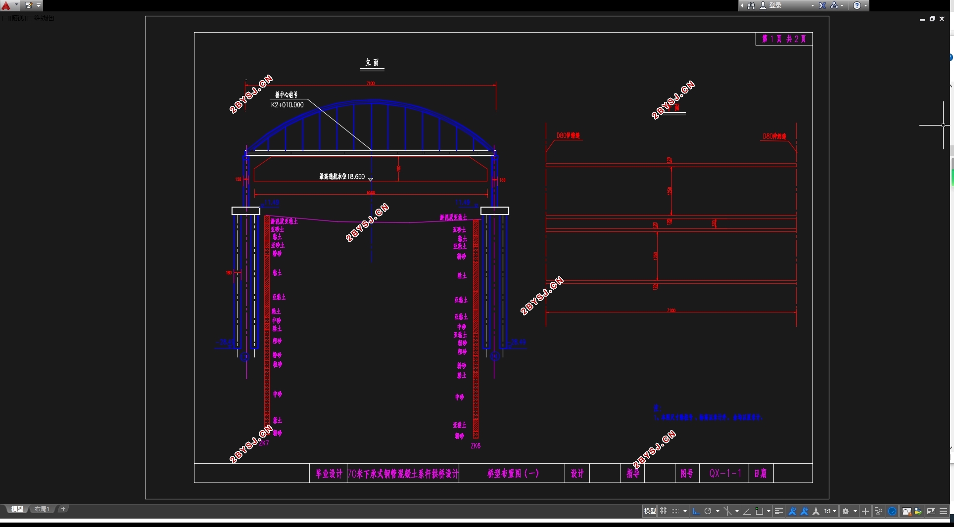
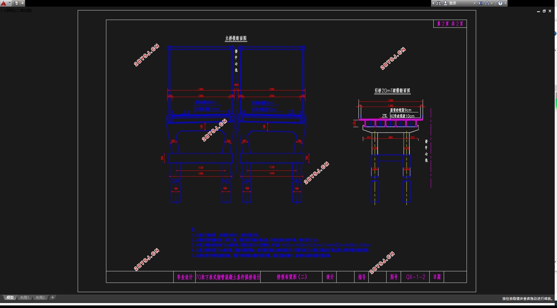
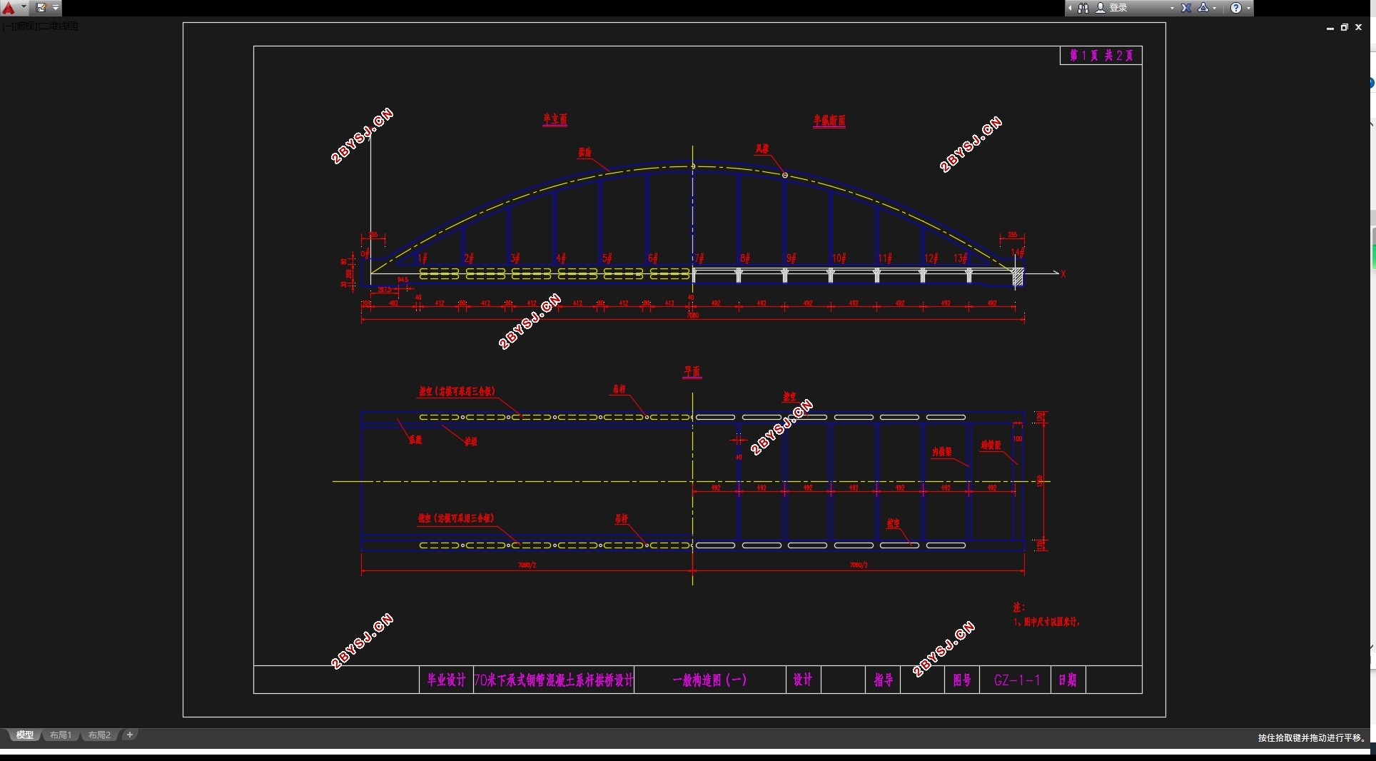
70m下承式钢管混凝土系杆拱桥设计(含CAD图,迈达斯模型)
无需注册登录,支付后按照提示操作即可获取该资料.
70m下承式钢管混凝土系杆拱桥设计(含CAD图,迈达斯模型)(任务书,开题报告,外文翻译,计算说明书14000字,CAD图22张,MIDAS模型)
摘要
本毕业设计题目为下承式钢管混凝土系杆拱桥,它的跨径是71m。这种桥型构造刚度好、行车平稳舒适、便于养护、抗震性能好。因此,在最近的这些年里,系杆拱桥的应用更加普遍。
本设计首先根据设计经验及构造要求拟定了主梁的主要构造和相关细部尺寸;考虑到桥梁所处的地形地貌,墩身采用了外柱高13.5m,内柱高13.25m的框架式桥墩;根据地质情况选用摩擦桩作为基础。其次确定施工方法,采用少支架现浇施工。
之后,利用MIDAS/CIVIL软件进行结构有限元分析。根据拟定桥梁尺寸建立桥梁基本模型,进行内力分析、预应力筋的估算与布置以及截面验算。建模时考虑了混凝土收缩徐变、温度、沉降等因素的影响,进行了相关次内力的分析。同时,进行了行车道板、锚下局部承压、桥墩及基础的相关手算。
经过分析验算表明,本次设计计算方法正确,内力分布合理,完成设计任务的要求。
关键词:下承式钢管混凝土系杆拱桥;结构分析;MIDAS/CIVIL
Abstract
The subject of this graduation project is "through concrete-filled steel tubular tied arch bridge". Its span is 71m. The bridge has the advantages of good structural rigidity, stable running, comfort, easy maintenance and good seismic performance, and the consolidation of pier and girder is beneficial to cantilever construction. Therefore, in recent years, the application of tied arch bridge is more common.
The first design according to the design experience and structural requirements to the main girder structure and the size of the details; considering the topography, The pier adopts a frame type abutment with a height of 13.5m and a height of 13.25m; according to the geological conditions as the basis for selection of friction pile. Secondly, the construction method is confirmed, and the cast-in-place construction with less support is adopted.
Then, the finite element analysis of structure is carried out by using MIDAS/CIVIL software. According to the size of the bridge, the basic model of the bridge is established. The internal force analysis, the estimation and arrangement of the prestressing force and the calculation of the section are carried out. The influence of concrete shrinkage, creep, temperature and settlement is taken into account when modeling, and the analysis of secondary internal forces is carried out. At the same time, the relevant calculation of the local pressure, the pier and the foundation of the slab, the anchor and the anchor is carried out.
The analysis and calculation show that the design calculation method is correct, the internal force distribution is reasonable, and the design task is completed.
Key words: through concrete-filled steel tube tied arch bridge; cantilever construction; structural analysis; MIDAS/CIVIL
其基本资料如下:
1、地形地貌
桥位所在地区为黄淮冲积平原之黄河高漫滩和冲积平原交界处,桥位区地面稍有起伏,沟塘较多。两侧河堤处相对较高,地面标高17.0~19.0m。两堤之间北侧为堆积漫滩,地面标高约15~18.5m,住有居民;南侧水域宽约 100m,河床南深北浅,河底标高7~11m。南堤外地面相对稍高,标高15.7~16.0m,种有水稻,北堤外地面相对稍低, 标高14.7~15.1m,种有玉米、黄豆、红薯等。
2、气象水文及水质
桥位区地处北温带南缘,具有季风性、过渡性气候特点,四季分明,冬冷夏热,年最高气温40℃,最低气温-16℃,平均气温14.1℃,年最大降雨量 1394.9mm,年均风速 3.1m/s。
桥位区地处淮、沭、泗水系,地表水发育,所跨京杭大运河为国家二级航道。桥位南端废黄河为天然分水岭。
桥位区均为低矿化度弱碱性水,对混凝土无腐蚀性。
3、工程地质
地质勘察提示,勘探深度内的地层为第四系全新统、更新统及第三系上新统堆积物,地层分布相对稳定,运河南、北岩性及工程地质特征有一定的差异,南侧稍差,北侧稍好。
桥位区亚砂土及砂土发育,层数多,厚度大,其中 3 层、5 层饱和亚砂土在运河南侧液化,北侧不液化,8 层及其以深砂土为不液化土层。自南向北液化程序逐渐减小,具有明显地段性。
钻探表明,9、10、11 层硬塑~坚硬状粘性土强度高,承载力大,可作桥基持力层。


目 录
摘要 I
Abstract III
第1章 桥梁总体设计概况 1
1.1 设计初始资料 1
1.2 桥梁设计的方案比较 1
1.2.1主桥桥型方案的比选 1
1.3设计基本资料 3
1.3.1总体设计 3
1.3.2主要技术指标 3
1.3.3主要规范、标准 3
1.3.4主要材料 4
1.4桥梁结构尺寸拟定与设计 4
1.4.1主桥上部结构拟定 4
1.4.2拱肋钢管混凝土结构拟定 5
1.4.3预应力加劲梁结构拟定 5
1.5主要结构施工流程 6
1.6 MIDAS/CIVIL建模 7
第2章 拱肋内力计算 16
2.1 恒载内力计算 16
2.1.1 概述 16
2.1.2 主跨部分截面几何性质及自重 16
2.1.3 工况 19
2.1.4 MIDAS/CIVIL模型单元参数汇总 19
2.1.5 计算结果汇总 20
2.2 内力组合 21
2.2.1 内力组合原则 21
2.2.2 内力组合结果 21
第3章 钢管混凝土拱肋验算 24
3.1 拱肋强度验算 24
第4章 构件强度验算 26
4.1 吊杆强度验算 26
4.1.1 概述 26
4.1.2 吊杆内力计算 26
4.2 系杆强度验算 28
4.2.1系杆预应力布置 28
4.2.2系杆内力包络图 33
4.2.3系杆验算 33
4.3 横梁预应力配束及损失估算 36
4.3.1 设计资料 36
4.3.2 横梁尺寸 37
4.3.3 横梁毛截面几何特性 37
4.3.4 主梁内力计算 37
4.3.5 预应力钢束面积的估算及钢束的布置 39
4.3.6 横梁截面几何特性计算 42
4.3.7 钢束预应力损失估算 42
4.3.8 预加应力阶段的正截面应力验算 45
4.3.9 使用阶段的正应力验算 45
4.3.10 使用阶段的主应力验算 47
4.3.11 横梁变形(挠度)计算 49
4.4 桥面板计算 50
4.4.1 概述 50
4.4.2 截面内力计算 51
4.4.3 配筋计算 52
4.4.4 截面复核 53
第5章 下部结构设计 53
5.1 下部结构尺寸拟定 53
5.1.1 墩身尺寸拟定 53
5.1.2 桩基础尺寸拟定 53
5.1.3 承台尺寸拟定 54
5.2 桥墩墩柱计算 54
5.2.1 墩柱材料 54
5.2.2 荷载计算 54
5.2.3 截面配筋计算 54
5.3 钻孔灌注桩计算 56
5.3.1 钻孔桩材料 54
5.3.2 荷载计算 54
5.3.3 桩长计算 58
5.3.4 桩的内力计算 59
5.3.5 桩基配筋计算及桩身材料截面强度验算 61
第6章 拱脚三维有限元模型 63
6.1建立拱脚模型 63
6.2模型建立步骤简述 63
致谢 68
参考文献 69
