80+100+80m的三跨变高度连续梁桥设计(含CAD图)
无需注册登录,支付后按照提示操作即可获取该资料.
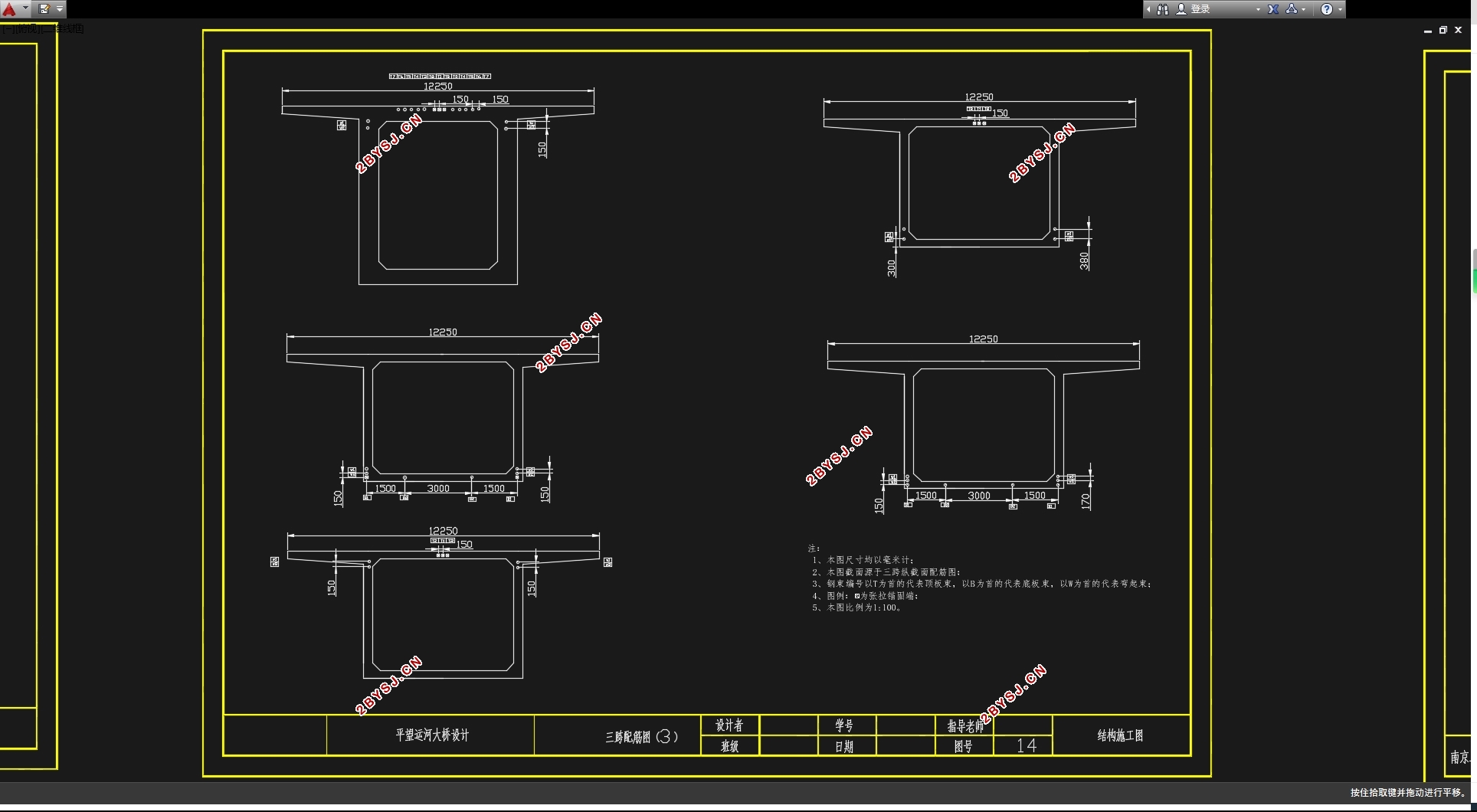
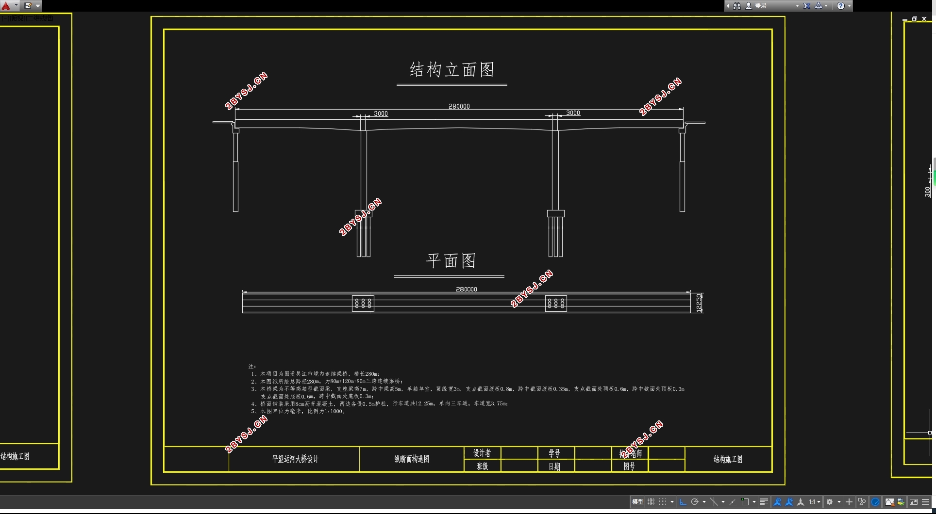
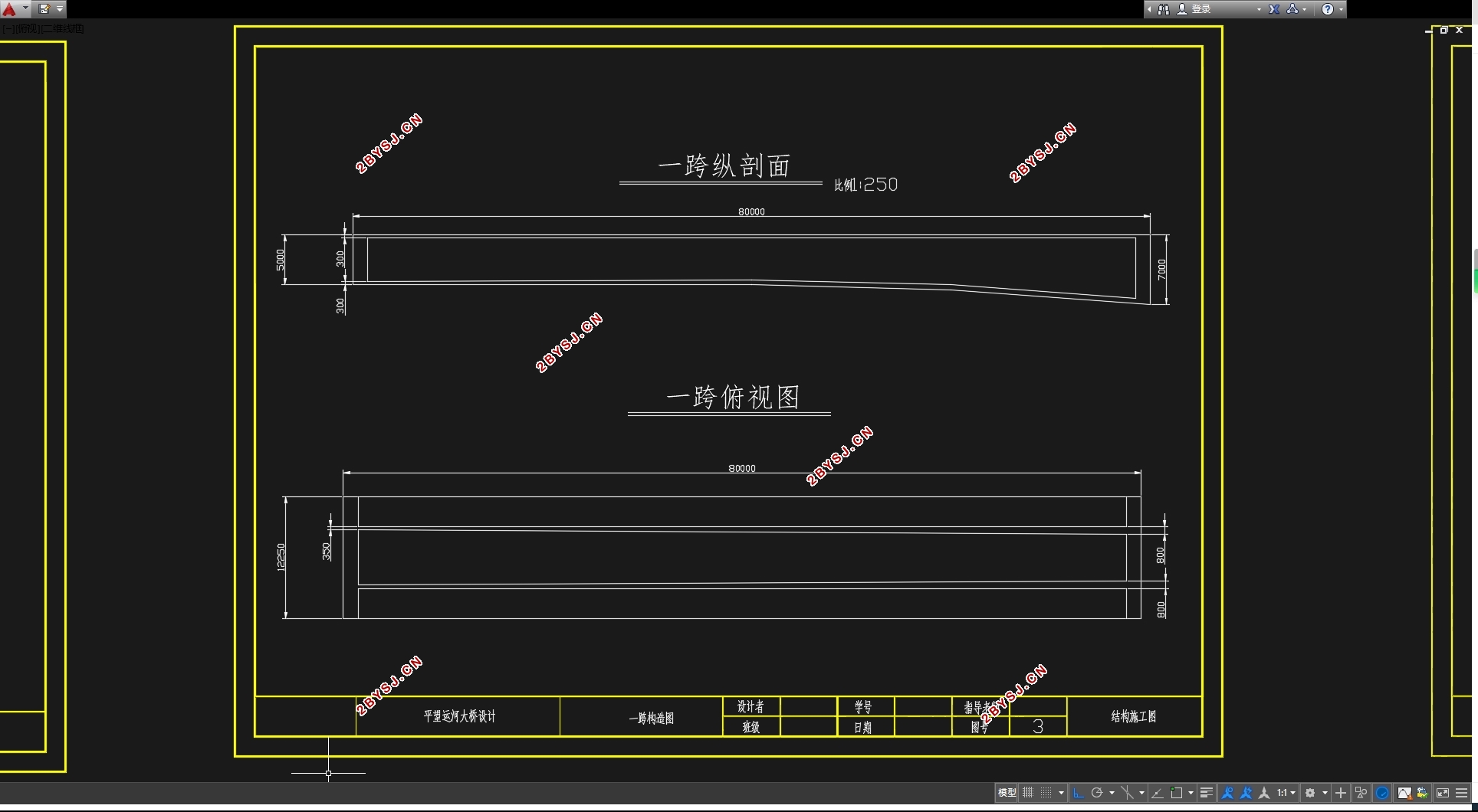
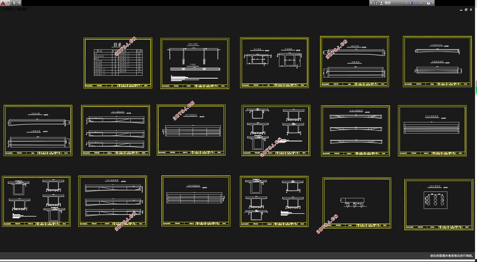
80+100+80m的三跨变高度连续梁桥设计(含CAD图)(任务书,开题报告,外文翻译,计算说明书20000字,CAD图16张)
摘 要
本设计为运河大桥,全长280米。初步方案拟定为80+100+80m的三跨变高度连续梁桥,根据桥面宽度和连续梁桥的受力特点,截面形式选择单箱单室,并拟定了箱梁各细部尺寸。然后,分别进行了箱梁自重、二期恒载、汽车作用、温度次内力和支座沉降次内力的计算,接着对上述内力,进行了荷载组合,包括基本组合、短期效应组合和长期效应组合。根据短期效应组合进行了桥跨结构的配筋设计,并完成了各项预应力损失的计算。最后,对结构进行承载力验算和使用阶段的正应力和主应力验算,验算结果表明,设计满足要求。
关键词:连续梁、满堂支架、内力、应力、验算
Design of approach bridge of flat inspection canal bridge
Abstract
The subject is the design of approach bridge of flat inspection canal bridge. a total length of 280 meters. Preliminary plan of 80+ 100+ 80m three span variable height of continuous beam bridge, according to the width of the deck and continuous girder bridge, cross section form selection of single box and one rooms, and worked out the detailed size of box beam. Then, were settlement calculation of box girder deadweight, two dead load, car function, temperature secondary internal force and secondary internal force, and then the internal force, the load combinations, including the basic composition, short-term effect and long-term effect combination combination. According to the short term effect of combination of bridge structure reinforcement design, and completed the prestressing loss calculation. Finally, the structure bearing capacity checking and using stage of normal stress and principal stress calculation, calculation results show that, the design meets the requirements.
Key words: continuous bridge; full framing; internal forces;stress;checking calculation;


目 录
摘要……………………………………………………………………………………………I
ABSTRACT…………………………………………………………………………………II
第一章 概述………………………………………………………………………………1
1.1 预应力混凝土连续梁桥概述……………………………………………….2
1.2 毕业设计的目的与意义………………………………………………………3
第二章 设计资料………………………………………………………………………5
2.1 工程概况及背景…………………………………………………………………5
2.2 主要技术标准及基础资料……………………………………………………5
2.3 桥梁设计的基本要求………………………………………………………….7
第三章 初步尺寸拟定……………………………………………………………….9
3.1 桥梁尺寸的拟定………………………………………………………………….9
3.2 桥面铺装……………………………………………………………………………10
第四章 荷载组合……………………………………………………………………….11
4.1 单元划分……………………………………………………………………………11
4.2 自重………………………………………………………………………………….12
4.3 铺装………………………………………………………………………………….14
4.4 汽车荷载……………………………………………………………………………15
4.5活载内力计算………………………………………………………………………15
4.6 支座沉降……………………………………………………………………………16
4.7 温度荷载……………………………………………………………………………17
4.8 内力组合……………………………………………………………………………20
第五章 预应力钢束的估算与布置…………………………………………………26
5.1 计算原则…………………………………………………………………………….26
5.2 钢筋数量的确定与布置…………………………………………………………28
5.3 截面几何特性………………………………………………………………………32
第六章 预应力损失计算…………………………………………………………………35
6.1 基本理论………………………………………………………………………………35
6.2 预应力损失计算……………………………………………………………………35
6.3 截面有效预应力……………………………………………………………………43
第七章 承载力验算…………………………………………………………………………44
7.1 基本原理…………………………………………………………………………….44
7.2 截面承载力计算……………………………………………………………………44
第八章 抗裂验算……………………………………………………………………………50
8.1 规范要求…………………………………………………………………………….50
8.2 计算结果…………………………………………………………………………….51
第九章 持久应力验算…………………………………………………………………….54
9.1 截面混凝土的正应力验算………………………………………………………54
9.2 持久状况下钢筋预应力验算……………………………………………………54
9.3 持久状况下混凝土主应力验算…………………………………………………62
第十章 挠度验算………………………………………………………………………………65
第十一章 下部尺寸的拟定………………………………………………………………66
参考资料……………………………………………………………………………………………69
致谢……………………………………………………………………………………………………70
