南京2700平米门式刚架轻钢结构金加工厂房设计(含建筑图结构图)
无需注册登录,支付后按照提示操作即可获取该资料.
南京2700平米门式刚架轻钢结构金加工厂房设计(含建筑图结构图)(任务书,开题报告,外文翻译,论文计算书12000字,CAD建筑图7张,CAD结构图10张)
摘要
门式刚架轻钢结构能有效地利用材料,构件尺寸小,重量轻,而且可以在工厂批量生产,保证质量,工地连接简便迅速,施工周期短。正因为这些优点,被广泛地应用在一般工业与民用建筑中。
根据毕业设计任务书的要求,分建筑和结构两部分进行设计。
建筑部分,将门式刚架厂房设计为3跨,每跨的间距为15m,总长度60m。该单层门式刚架结构是以轻型焊接H型钢作为主要承重骨架,用冷弯薄壁型钢(C型)做檩条、墙梁;以压型钢板做屋面、墙面.
结构部分,查阅相关规范和一定量的实际工程设计图,对每榀刚架的最不利荷载进行计算,使用PKPM软件完成刚架的合理截面计算,然后通过设计规范的相关要求,对刚梁、柱、支撑、檩条等构件进行稳定性计算。
关键词:门式刚架 建筑 结构 规范
Abstract
Portal frame light steel structure effective use materials,component size is small ,light weight,and in the factory mass production,quality assurance,site connection is simple and rapid,short construction period.Precisely because of these advantage,has been widely used in general industrial and civil buildings.
According to the requirements of the design plan, descriptions of the graduation points two parts,architectural and structural design.
Construction part, by looking at other relevant information, the door type rigid frame factory building design for 3 across, each across the span of 15m, total length of 60m. The single layer type of door rigid frame structure with light weldingh-beam as the main load-bearing skeleton, with cold-formed thin-walled steel purlin, (C)do wall beam; In order to do roofing, wall steel sheet; Using 80mm glass wool as the thermal insulation material and appropriate Settings to support a lightweight building structure system.
Structural part, according to related specification and a certain amount of practical engineering design, for every nature, the most unfavorable load calculation of the frame, using PKPM software to complete the reasonable cross section frame calculation, and then through the design specification, the requirements of the relevant on beam, column, supports, purlin artifacts such as stability calculation, respectively with AUTOCAD2008 map design.
Key word:Portal frame architecture structure specification
1.1.2工程地点:南京
1.1.3已确定的设计初步方案:
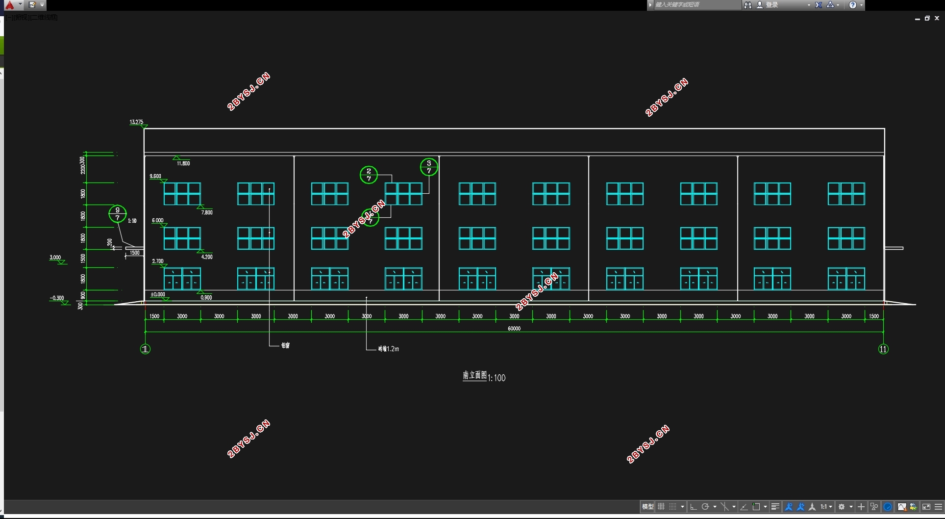
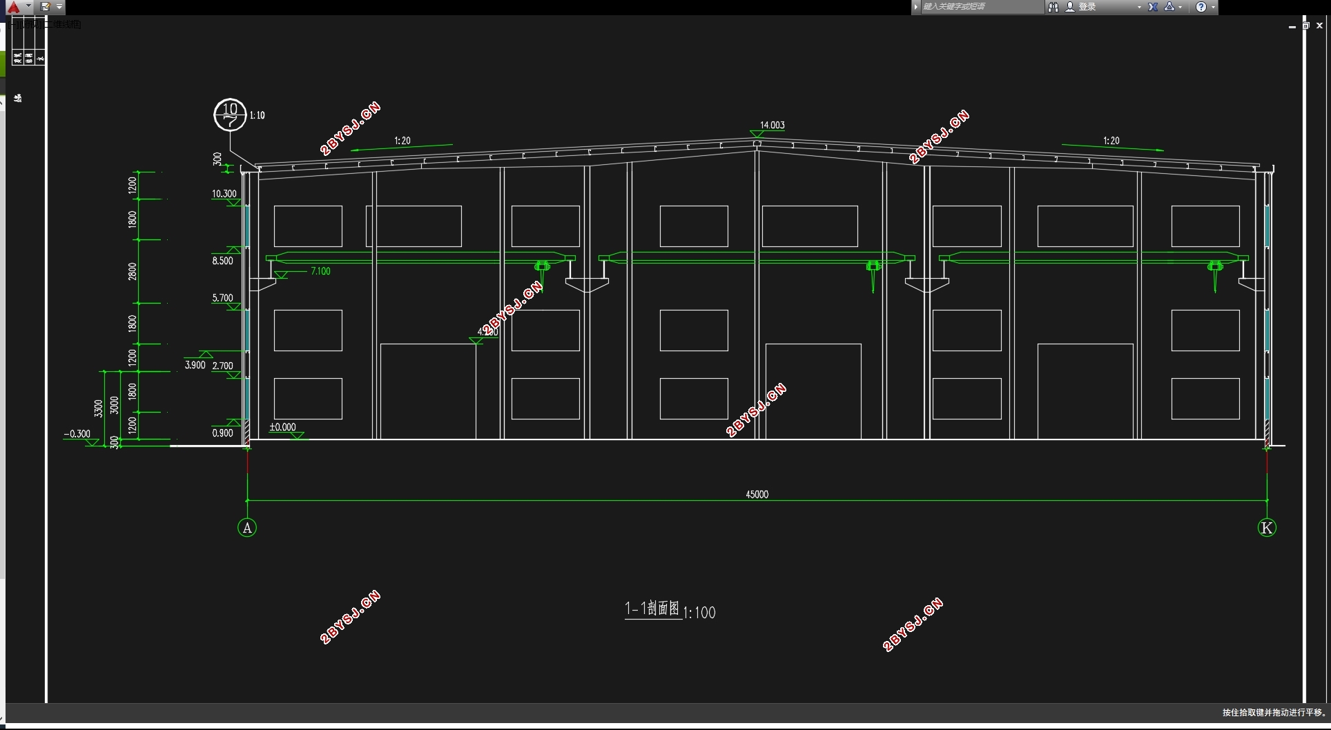
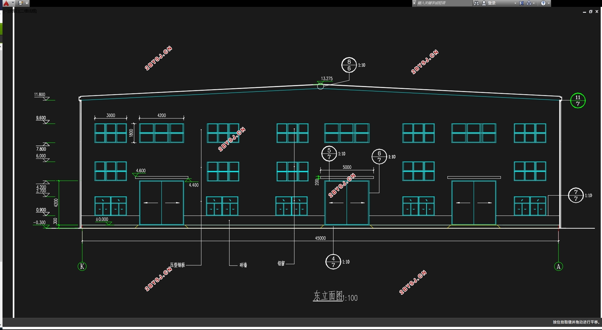
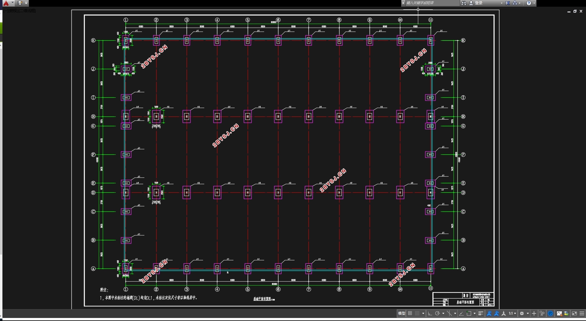
本工程三跨双坡双脊单层轻型门式刚架钢结构厂房,每跨跨度15m,刚架间距6.0m,平面轴线尺寸为60m×45m,每跨内设置起重量为10tA5级电动单梁吊车1台。建筑总平面示意图、初步确定的柱网布置、建筑剖面见附图。
目录
第一章 设计资料 1
1.1工程概况 1
1.2设计内容和要求: 2
1.3参考文献: 2
第二章 建筑设计及结构的选型与布置 5
2.1建筑设计 5
2.1.1 建筑布局 5
2.1.2 主体厂房设计 5
2.2.3 屋面、墙面设计 5
2.1.4门窗设计 5
2.2 结构的选型与布置 5
2.2.1 结构布置 5
2.2.2 结构构件选型 6
2.2.3 基础类型 6
2.2.4构造说明 6
第三章 结构设计 8
3.1压型钢板的设计 8
3.1.1内力计算 8
3.1.2截面几何特征计算 8
3.1.3有效截面计算 9
3.1.4强度验算 10
3.1.5刚度验算 11
3.2檩条设计 11
3.2.1设计资料 11
3.2.2永久荷载(水平投影面) 11
3.2.3内力计算 11
3.2.4 截面选择 13
3.3墙梁设计及拉条设计 16
3.3.1设计资料与说明 16
3.3.2荷载及内力计算 16
3.3.3 截面选择 17
3.4工字形吊车梁设计 18
3.4.1设计资料 18
3.4.2吊车荷载计算 18
3.4.3内力计算 18
3.4.4截面选择 19
3.4.5强度计算 21
3.4.6稳定计算 22
3.4.7挠度计算 22
3.4.8支座加劲肋计算 22
3.4.9疲劳强度计算 23
3.4.10焊缝计算 23
3.5刚架主体设计 24
3.5.1截面选型 24
3.5.2荷载计算 26
3.5.3恒荷载作用下的内力图(采用力法) 26
3.5.4内力组合 30
3.6刚架梁、柱截面验算 41
3.6.1刚架梁 41
3.6.2有效截面特性 41
3.6.3刚架梁的验算 44
3.6.4刚架边柱 47
3.6.5刚架中柱 52
3.7.节点设计 56
3.7.1梁柱、梁梁节点设计 56
3.7.2 牛腿设计 61
3.7.3 柱脚设计 64
3.8基础设计(独立) 67
3.8.1边柱住下独立基础设计 67
3.8.2中柱住下独立基础设计 70
第四章工程量及简要技术经济分析 73
结束语 74
致谢 75
