二十一层商住楼的建筑给排水设计(含CAD图)
无需注册登录,支付后按照提示操作即可获取该资料.
二十一层商住楼的建筑给排水设计(含CAD图)(任务书,开题报告,外文翻译,计算说明书20000字,CAD图20张)
摘 要
本设计是某二十一层商住楼的建筑给排水设计,主要包括建筑给水系统、排水系统、雨水系统,消防系统等四部分设计。
给水系统分为三个区供水:地下一层至二层为低区,由市政管网直接供水;三至十二层为中区,十三至二十一层为高区,由变频泵供水。排水系统采用的是雨污分流、污废合流制,雨水直接排入市政雨水管网,卫生间污水经化粪池处理后排入市政污水管网,厨房废水经隔油池处理后排入市政管网;1-2层排水立管设伸顶通气,3-21层排水立管设有专用通气立管。消防系统分消火栓系统和自动喷淋灭火系统两部分。消火栓系统不分区,采用SN65型消火栓。自喷系统,-1层至23层设自喷系统,-1层采用中危Ⅱ级标准,其他采用中危Ⅰ级标准。自喷系统与消火栓系统合用消防水箱。给水管材根据需要,卫生间采用塑料管(UPVC),住宅给水干管采用PPR塑料管。同时在穿墙处设阻火圈,在出户管相连处设一定的消能措施。消防系统采用镀锌钢管。
关键词:高层建筑,给水系统,排水系统,消防系统,自动喷淋系统
Abstract
This design is a 21 layer near the building water supply and drainage design, including building water supply system, drainage system, rain water system, fire protection system and so on four parts design.
Water supply system is divided into three district water supply: layer to the second floor underground are used for lower area, water supply directly by the municipal pipe network; Three to ten second to the central, the 13th to the 21st layer is high area, by frequency conversion water supply pump. Rain drainage system USES is the unclean shunt, confluence system, waste water is directly discharged into municipal rainwater pipe network, toilet wastewater treated by septic tank back into the municipal sewage pipe network, kitchen waste water treated by separation tank back into the municipal pipe network; 1-2 layer set and roof ventilation, drainage riser layer 3-21 drainage riser is equipped with special ventilation pipe. Fire hydrant system and automatic fire control system spray extinguishing system two parts. Don't fire hydrant system partition, using SN65 type hydrant. Flowing system, 1 set to 23 layer flowing system, 1 layer adopts the Ⅱ level standard, other USES in the dangerous Ⅰ level standard. Flowing system and hydrant system share fire water tank. Water supply pipe according to need, toilet USES plastic pipes (UPVC), water main residential use PPR plastic pipes. Set fire collars in the wall, at the same time in their homes for tube connected to a certain energy dissipation measures. Fire control system are made of galvanized steel pipe.
Key Words: high-rise buildings, water supply system, drainage system, fire-fighting system, automatic sprinkler system
工程概况及设计资料
第一章 工程概况及设计资料
1.1设计题目
瑞源商住楼A座给水排水设计
1.2建筑物介绍
1.2.1环境介绍
市政自来水压力约为: 0.25MPa。
1.2.2建筑物介绍
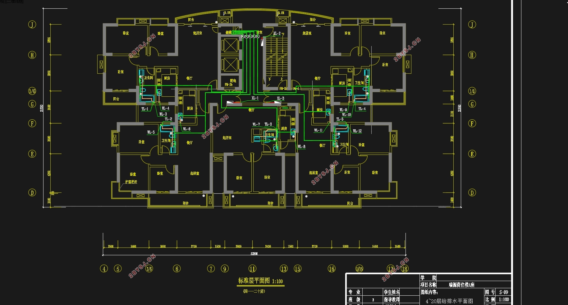
瑞源商住楼A座主体建筑为地上二十一层,地下一层。地下一层为车库、地上一至二层为商场,三至二十一层为住宅,其中二十一层为跃层,总建筑面积19800m2,建筑总高度73.70m。
1.3工程设计
1.3.1设计内容
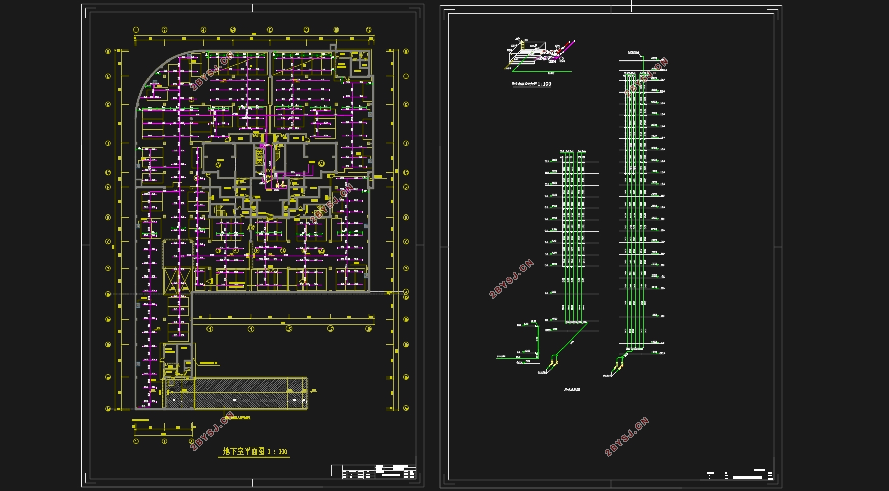
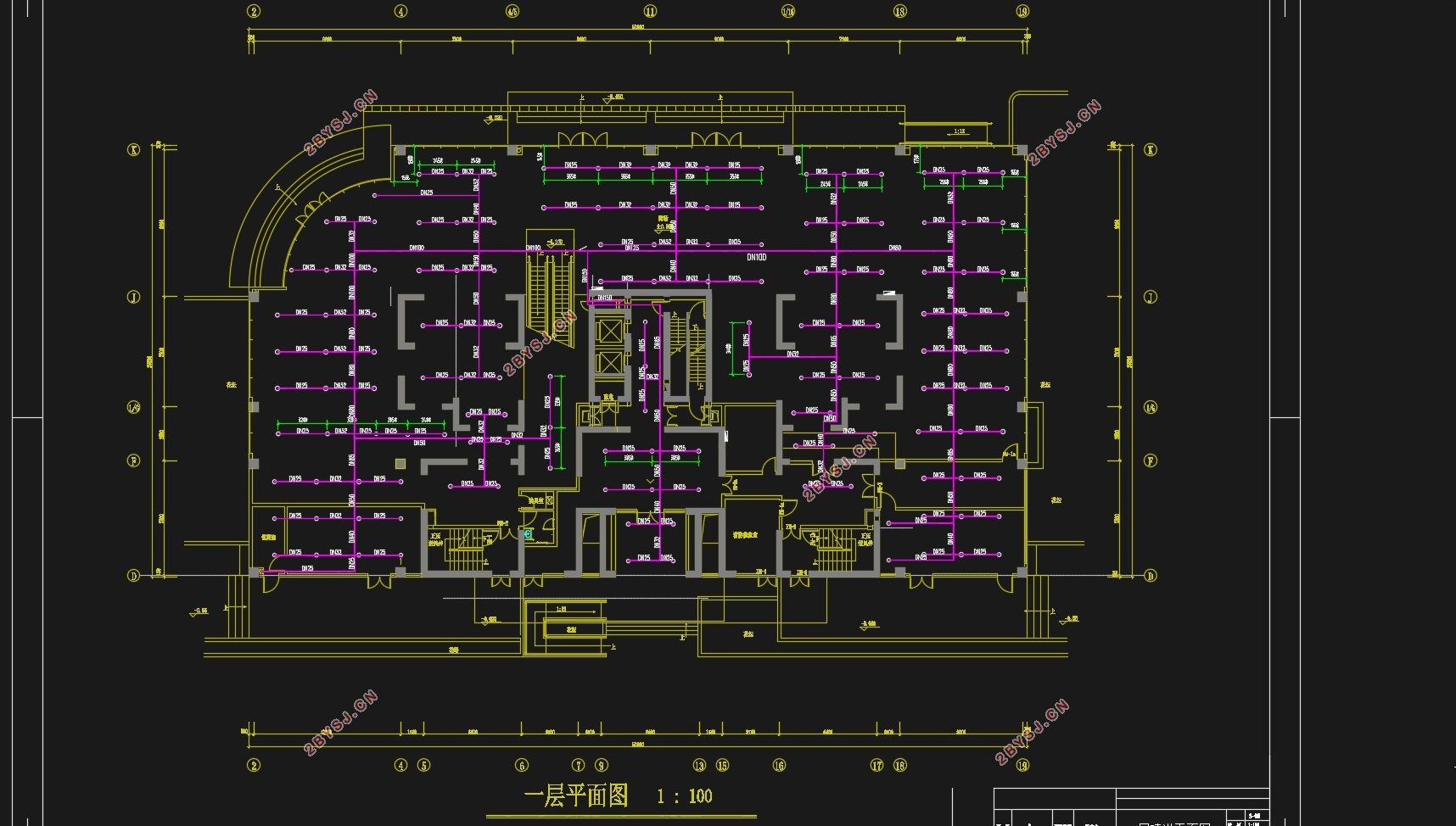
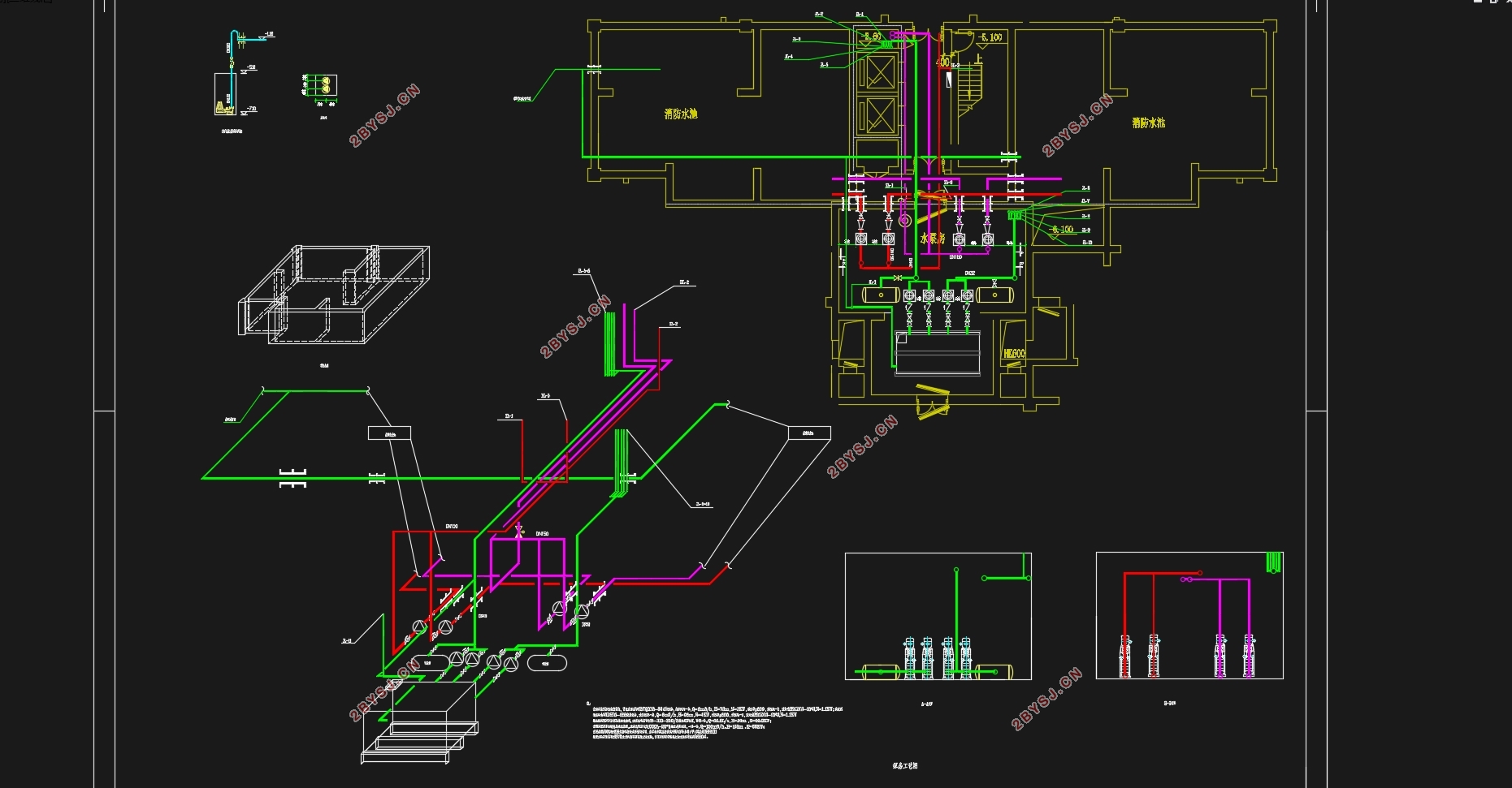
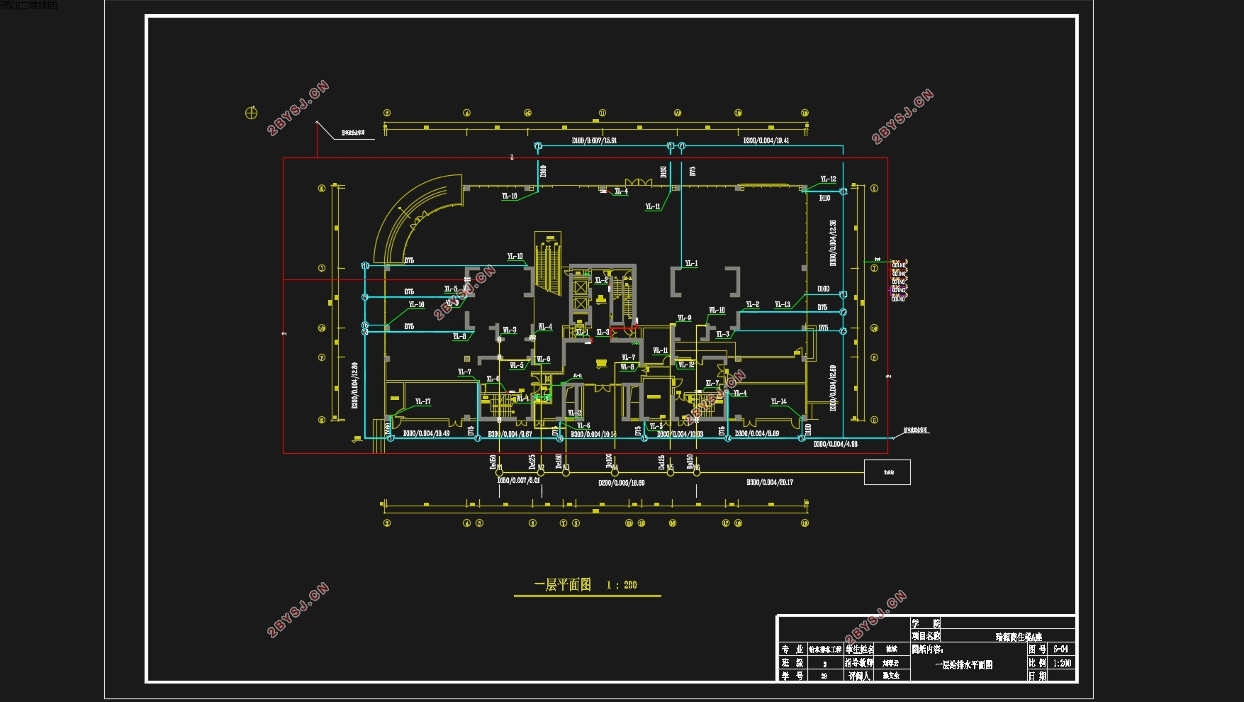
设计该建筑给水系统,室内排水系统,消防系统,室外雨水排放系统。
目录
第一部分 工程概况及设计资料 1
第一章 工程概况及设计资料 1
1.1设计题目 1
1.2建筑物介绍 1
1.3工程设计 1
第二部分 设计说明书 3
第一章 给水系统设计计算说明 3
1.1 给水系统的竖向分区 3
1.2 给水管道的布置 7
第二章 排水系统设计说明 9
2.1室内污水的分类 9
2.2污水系统的组成 9
2.3管材的选择 9
2.4管道的布置 10
2.5排水管道的连接 11
2.6地漏 11
2.7检查口 11
2.8清扫口 11
第三章 雨水系统设计说明 11
第四章 消火栓系统设计说明 13
4.1 建筑物分类和火灾危险等级的确定 13
4.2消火栓给水系统的分类 13
4.3消火栓系统的比较 14
4.4消火栓给水系统的选择 15
4.5 消火栓系统的组成 16
4.6 布置消火栓、管道 16
第五章 喷淋系统设计说明 16
5.1自动喷淋系统概述 16
5.2 自动喷淋系统的分类 18
5.3自动喷淋系统的选择 19
5.4喷头的设计参数 20
5.5 喷头布置 20
5.6 自动喷水灭火系统管道及阀门等设置 22
5.7 管材的选择 23
第三部分 设计计算书 24
第一章 建筑给水系统设计计算 24
1.1 生活用水低位贮水池容积计算 24
1.2 给水系统水力计算 24
第二章 建筑排水系统设计计算 34
2.1 计算依据 34
2.2 排水系统水力计算 41
2.3 化粪池容积计算 45
2.4 潜污泵选择 46
第三章 建筑雨水系统设计计算 48
3.1计算依据 48
3.2 雨水计算表格 48
第四章 消火栓系统设计计算 49
4.1消火栓的保护半径和间距 49
4.2水枪喷嘴处所需的水压 49
4.3 水水枪喷嘴出流量 50
4.4水带阻力 50
4.5消火栓口所需的水压 50
4.6校核 50
4.7水力计算 51
4.8 消火栓减压 53
第五章 喷淋系统设计计算 55
5.1 商场自喷水量的计算 55
5.2 住宅自喷水量的计算 58
5.3 消防水箱 59
5.4 消防贮水池 59
5.5 水泵接合器 59
结 论 60
致 谢 61
