
三河大桥(64+116+64m)预应力混凝土连续刚构桥上部结构设计(含CAD图)
无需注册登录,支付后按照提示操作即可获取该资料.
三河大桥(64+116+64m)预应力混凝土连续刚构桥上部结构设计(含CAD图)(任务书,开题报告,设计说明书28000字,CAD图纸32张)
摘要
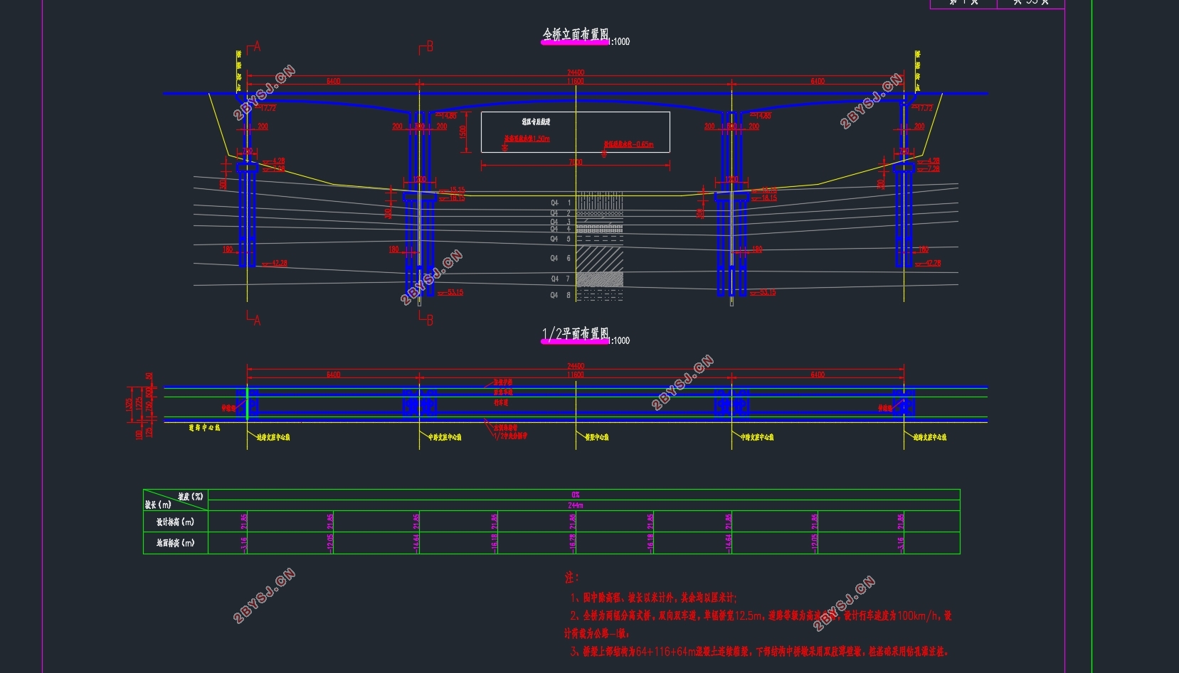
本次设计题目为三河大桥上部结构设计和计算分析。三河大桥是一座预应力混凝土连续刚构桥,跨径为64+116+64m,主要采用悬臂浇筑法施工。设计步骤如下:
首先,根据初始资料及通过已有桥梁数据拟定主梁跨中及支点处截面尺寸。截面形式为单箱单室,主梁采用变截面梁,线性为二次抛物线,主梁节段为2~4m,合龙段2m。单幅桥宽12.25m,中支点处梁高7.0m,跨中处梁高2.5m,墩顶设置有横隔板。
然后利用迈达斯软件建立有限元模型,模拟结构实际受到的荷载、边界条件和施工过程。全桥共170个节点,153个单元,其中主梁划分为93个单元,墩柱划分为60个单元,施工阶段共划分为73个。
利用初步完成的模型计算结构内力及次内力,并进行第一次荷载组合。使用承载能力极限状态基本组合,按照全预应力构件在使用阶段截面上下缘不得出现拉应力的原则,计算配置纵向预应力钢束,设置预应力荷载,进一步完善模型。
重新计算结构次内力,并进行第二次荷载组合。按规范进行各项验算,调整设计直至验算全部通过。
最后绘制施工图,编写计算说明书。
通过这次设计,完成对预应力混凝土连续刚构桥上部结构的设计和计算分析,并掌握预应力混凝土连续刚构桥的结构形式、细部构造、受力特点、设计计算方法、施工方法,熟悉相应设计规范及结构构造要求,熟练桥梁施工图的绘制。
关键词:预应力混凝土;连续刚构桥;有限元分析;悬臂施工;设计
Abstract
The design topic is the design and calculation of the upper structure of Sanhe Bridge. It is a prestressed concrete continuous rigid frame bridge with a span of 64+116+64m. It is mainly constructed by the cantilever method. The design steps are as follows:
First, based on the initial data and the existing bridge data, the cross-sectional dimensions at the midspan and the fulcrum of the main beam are determined. The cross section is in the form of a single box, with a variable cross-section girder for the main girder, a quadratic parabola for the linear, a section of the main girder of 2 to 4 m, and a length of 2 m for the girder section. The single-beam bridge is 12.25m wide, with a beam height of 7.0m at the mid-column point and 2.5m high at the mid-span beam, with diaphragms at the top of the pier.
Then use Midas to build a finite element model to simulate the loads, boundary conditions, and construction processes that the structure actually receives. The whole bridge has a total of 170 nodes and 153 units, of which the main beam is divided into 93 units and the pier columns are divided into 60 units. The construction period is divided into 73 units.
Use the initially completed model to calculate the internal and secondary internal forces of the structure and perform the first load combination. Using the basic combination of the ultimate state of carrying capacity, according to the principle of no tensile stress at the upper and lower edges of the full-prestressed component in the use phase, the longitudinal pre-stressed steel beam is calculated and pre-stressed loads are set to further improve the model.
Recalculate the structural internal forces and perform the second load combination. According to the specifications for various checks, adjust the design until the check all passed.
Finally, draw the construction drawings and prepare the calculation instructions.
Through this design, the design and calculation of the superstructure of the prestressed concrete continuous rigid frame bridge are completed, and the structural form, detailed structure, force characteristics, design calculation method and construction method of the prestressed concrete continuous rigid frame bridge are mastered. Corresponding design specifications and structural requirements, skilled bridge construction drawing.
Key Words:Prestressed concrete; continuous rigid frame bridge; finite element analysis; cantilever construction; design
主要技术指标
(1)孔跨布置:三跨连续刚构桥,跨径布置为64m+116m+64m,边跨跨径64m,中跨跨径116m。边跨与中跨的比值为0.55,桥梁全长244m。
(2)中间墩高及类型:双肢空心薄壁墩,根据地形条件设计墩高30m。
(3)汽车荷载:等级为公路-I级。根据《公路桥涵设计通用规范 JTG D60-2015》的4.3.1条对公路-I级荷载的有关规范,得到本桥的设计荷载。
规范规定当计算跨径大于50m时,公路-I级车道荷载均布荷载标准值为 ,集中荷载标准值 。计算剪力效应时,上述集中荷载标准值应乘以系数1.2,车道荷载的计算图示如图2.1所示。车道荷载横向分布系数取0.78,不考虑纵向折减。
(4)桥面宽度: 2×[0.50m防撞栏杆+11.75m车行道(3m紧急停靠+7.5m车行道+1.25m左路沿带)+2m/2中央分隔带]=26.5m,上、下行车道分离式布置。
(5)桥涵净空:考虑桥梁跨域河道通航净空宽度、高度以及过水断面对设计洪水流量、洪水位高程等要求,并结合规范中的有关规定,本桥桥下净空宽度为70m,净空高度为15m。桥面净空高度5m。
目 录
第一章绪论 1
1.1 设计总体概述 1
1.2 设计基本流程 1
1.3 毕业设计的目的和意义 2
第二章设计依据及设计计算资料 4
2.1 地质资料 4
2.2 设计规范 4
2.3 主要技术指标 4
2.4 材料性能指标 5
2.4.1 主梁混凝土 5
2.4.2 中间墩及桥面铺装混凝土 6
2.4.3 主梁纵横向预应力钢绞线 6
2.4.4 预应力锚具规格 6
第三章桥梁总体布置及有限元模型建立 8
3.1 截面尺寸 8
3.1.1 主梁尺寸 8
3.1.2 墩柱尺寸 9
3.2 主梁节段 9
3.3 施工阶段 10
3.4 建立结构模型 11
3.4.1 建立节点和单元 11
3.4.2 定义边界条件 12
3.4.3 设置荷载和支座沉降 12
3.4.4 模拟施工阶段 13
第四章结构内力计算 14
4.1 毛截面特性计算 14
4.2 结构内力计算 15
4.2.1 结构重力作用下结构内力 15
4.2.2 混凝土收缩徐变次内力 22
4.2.3 基础变位作用次内力 25
4.2.4 汽车荷载作用下的结构内力 28
4.2.5 温度作用次内力 31
4.3 第一次荷载组合 36
第五章纵向预应力钢束设计 40
5.1 预应力钢束估算原理 40
5.2 预应力钢束估算 41
5.3 预应力钢束布置 42
第六章结构次内力计算与荷载组合 45
6.1 结构次内力计算 45
6.1.1 混凝土收缩徐变次内力 45
6.1.2 基础变位作用次内力 48
6.1.3 温度作用次内力 50
6.1.4 预加力作用次内力 54
6.2 第二次荷载组合 56
6.2.1 承载能力极限状态 56
6.2.2 正常使用极限状态 59
第七章截面验算 66
7.1 施工阶段法向应力验算 66
7.2 受拉区钢筋的拉应力验算 67
7.3 使用阶段截面抗裂验算 69
7.3.1 正截面抗裂验算 69
7.3.2 斜截面抗裂验算 70
7.4 使用阶段截面压应力验算 71
7.4.1 正截面压应力验算 72
7.4.1 斜截面主压应力验算 73
7.5 使用阶段正截面抗弯验算 74
第八章总结与讨论 77
参考文献 78
致谢 79