苏州8736平米养老院工程暖通空调系统设计(含CAD图)
无需注册登录,支付后按照提示操作即可获取该资料.
苏州8736平米养老院工程暖通空调系统设计(含CAD图)(任务书,开题报告,设计说明书21000字,CAD图纸21张)
摘 要
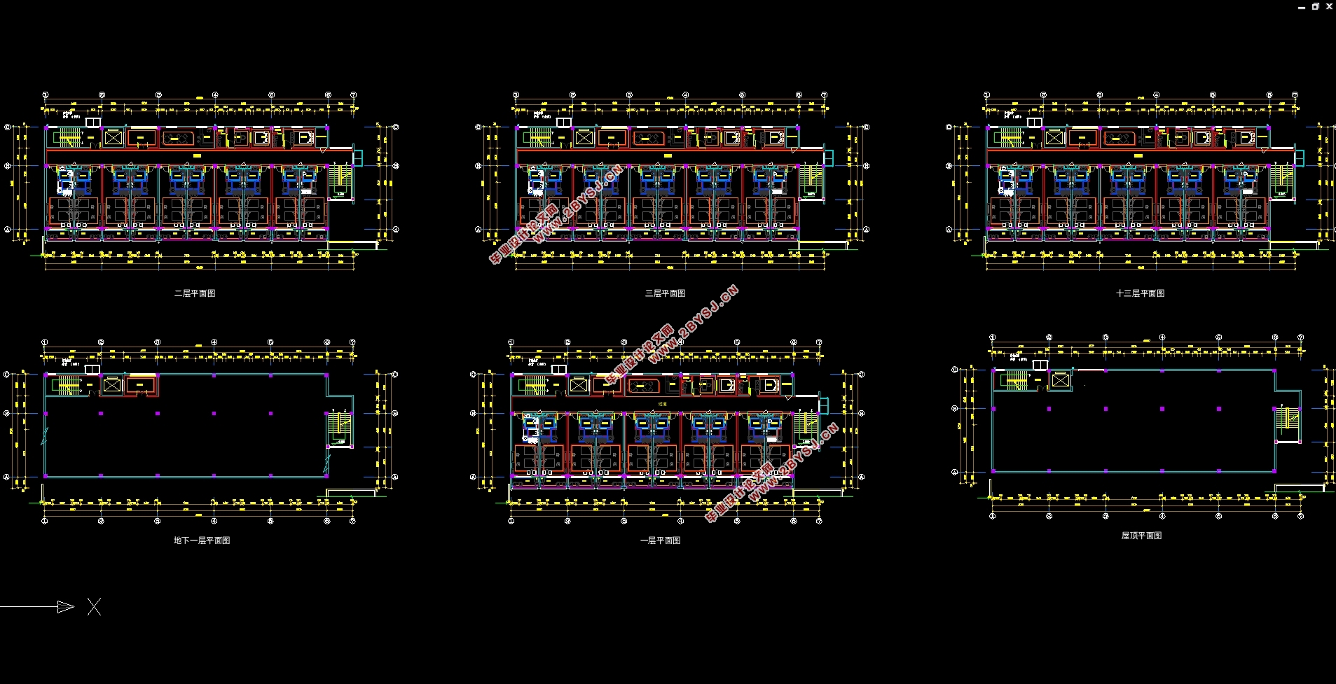
本建筑为养老设施建筑,所在地为江苏省苏州市,建筑总面积8736m2,地下一层,层高4.2m,地上十三层,层高3.6m。建筑的类型为多层建筑,耐火等级为一级。
本项目的冷热源经过技术性分析后,选定了冷水机组+锅炉以及地表水源热泵机组这两种方案,经过能耗分析和经济性分析,并考虑到施工的技术难度,最终确定冷热源方案为冷水机组+锅炉。
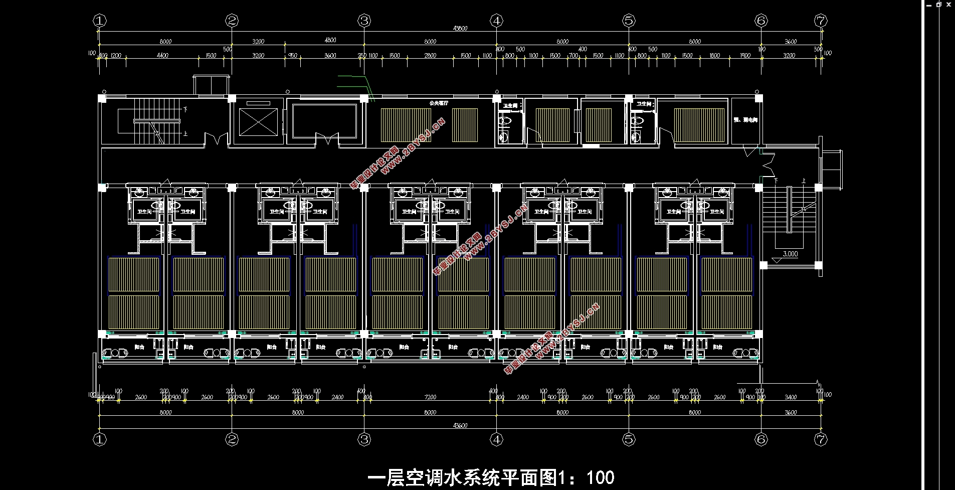
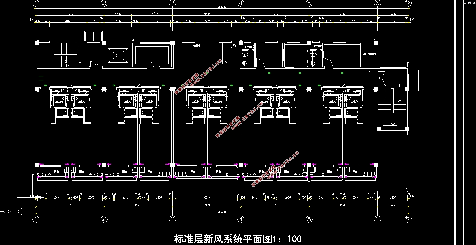
采用毛细管网末端的温湿度独立控制系统,夏季新风经低温冷冻水冷凝除湿后送入室内承担室内湿负荷、潜热负荷以及部分显热负荷,管内通入高温冷冻水的毛细管网承担室内显热负荷。冬季新风经新风机组加热后送入室内,室内热负荷全部由毛细管网辐射末端承担。
本系统设计的主要运行策略主要有压差旁通控制策略和露点监控策略。
关键词:辐射空调冷水机组露点独立新风
Suzhou Wangzi gerocomium HVAC system design
Abstract
The building is an old-age facility building, located in Suzhou, Jiangsu Province, with a total area of 8736 m2, one floor underground, 4.2 m high, thirteen floors above ground and 3.6 m high. The type of building is multi-storey building, fire-resistant grade is one.
After technical analysis of the cold and heat sources of this project, two schemes of chiller + boiler and surface water source heat pump unit are selected. After energy consumption analysis and economic analysis, and considering the technical difficulty of construction, the cold and heat source scheme is finally determined as chiller + boiler.
The temperature and humidity independent control system at the end of the capillary network is adopted. The fresh air in summer is condensed and dehumidified by cryogenic chilled water and then sent into the room to bear indoor humidity load, latent heat load and partial sensible heat load. The capillary network with high temperature chilled water in the tube bears indoor sensible heat load. In winter, fresh air is heated by the fresh air unit and sent into the room. The indoor heat load is borne by the radiation end of the capillary network.
The main operation strategies of the system design include differential pressure bypass control strategy and dew point monitoring strategy.
Key Words:Radiantairconditioning, Water chiller, Dewpoint, DOASs
建筑基本信息
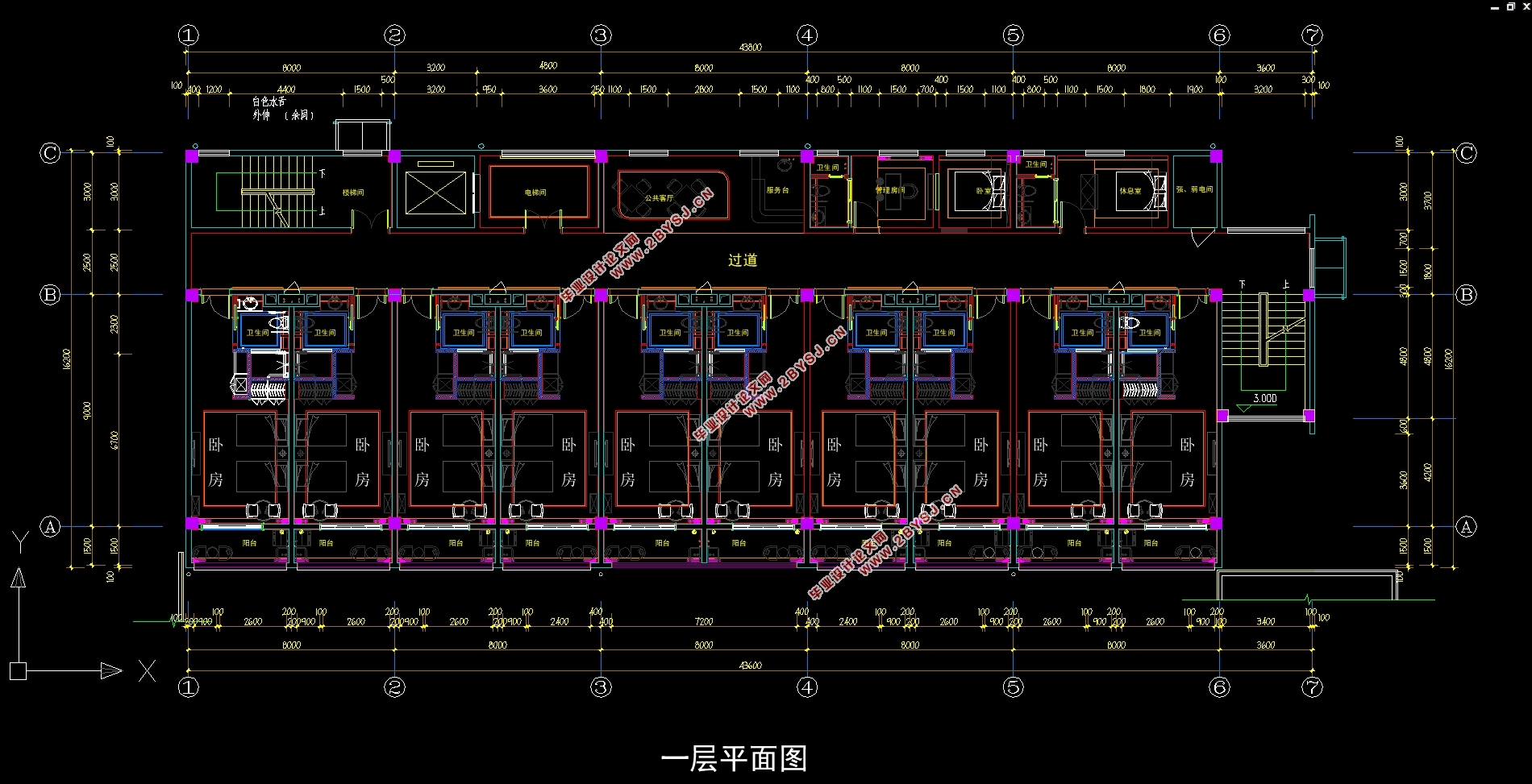
本建筑为养老设施建筑,建筑总面积8736m2,地下一层,层高4.2m,地上十三层,层高3.6m。建筑的类型为多层建筑,耐火等级为一级。
建筑的主要功能为:地下一层为设备用房,地上所有层均用于提供养老服务,主要有卧室、办公室、客厅和休息室,屋顶天台可用于布置少量设施设备。
建筑内部房间门高度均为2.4m,窗高2.0m,窗台距地板高度0.7m,各卧房的阳台与室内间的推拉门高度为2.7m。
本建筑空调区域为卧房、公共客厅、过道、管理房间和休息室,机房层、楼梯间、电梯间、阳台和卫生间不作为空调区域,空调区域面积4970m2。


目录
摘要 I
Abstract II
第一章项目概况 1
1.1 建筑概况 1
1.1.1 建筑基本信息 1
1.1.2 周边资源情况 1
1.1.3 围护结构热工参数 2
1.2 设计要求 3
1.3 设计参数 5
1.3.1 室内设计参数 5
1.3.2 室外计算参数 7
第二章负荷计算与分析 9
2.1 建筑全年动态负荷模拟 9
2.2 典型房间负荷计算验证 10
2.2.1 夏季设计日逐时冷负荷 10
2.2.2 冬季负荷指标法核算 15
2.3 负荷计算结果汇总与分析 15
2.3.1 负荷计算结果汇总 15
2.3.2 全年空调季度划分 16
2.3.3 空调季负荷率统计 17
第三章空调方案设计 18
3.1 空调方案选择 18
3.1.1 空调方案选择背景 18
3.1.2 所选方案的特点 18
3.2 新风处理方案 20
3.2.1 新风处理方案说明 20
3.2.2 室内新风计算结果汇总 23
3.2.3 新风机组选型 26
3.3 毛细管网末端方案 26
3.3.1 毛细管末端设备选型 27
3.3.2 毛细管网面积计算 28
3.3.3 毛细管网实际传热量校核 30
第四章冷热源系统方案设计 32
4.1 方案初选 32
4.2 方案比对 33
4.2.1 初投资比较 33
4.2.2 机组初步选型 33
4.2.3 能耗分析 34
4.2.4 运行费用比较 35
4.3 方案确定 35
第五章风系统设计计算 37
5.1 气流组织设计校核 37
5.2 新风系统水力计算 37
第六章水系统设计计算 40
6.1 冷冻水系统 40
6.1.1 系统设计概述 40
6.1.2 末端冷冻水系统水力计算 40
6.1.3 冷冻水系统附属设备选型 43
6.2 冷却水系统 44
6.2.1 系统设计概述 44
6.2.2 设备计算选型 44
6.3 冷凝水系统 47
6.4 热水系统 47
6.4.1 锅炉热水循环系统 47
6.4.2 锅炉补水系统 48
6.5 附属设备选型 49
6.5.1 水处理器 49
6.5.2 燃气部分计算 50
6.5.3 膨胀水箱 51
第七章空调系统运行策略 53
7.1 末端冷冻水系统的监控: 53
7.2 露点控制策略 53
第八章通风系统设计 55
8.1 送风系统 55
8.1.1 送风量计算 55
8.1.2 风口选型 55
8.1.3 送风管路水力计算 55
8.1.4 风机选择 55
8.2 排风系统 56
8.2.1 排风量计算 56
8.2.2 风口选型 56
8.2.3 排风管路水力计算 56
8.2.4 风机选型 56
