中级轿车驱动桥设计(含CAD零件图装配图,CATIA三维图)
无需注册登录,支付后按照提示操作即可获取该资料.
中级轿车驱动桥设计(含CAD零件图装配图,CATIA三维图)(任务书,开题报告,文献摘要,外文翻译,论文说明书13000字,CAD图6张,CATIA三维图)
摘要
现当今,经济社会高速发展,汽车工业的发展也正处于高速之中,汽车技术也处于高速列车之上,相应的汽车驱动桥的工艺等方面也在不断进步,不断的出现新的技术,同时其生产也在朝着“三大化”的方面不断靠拢。
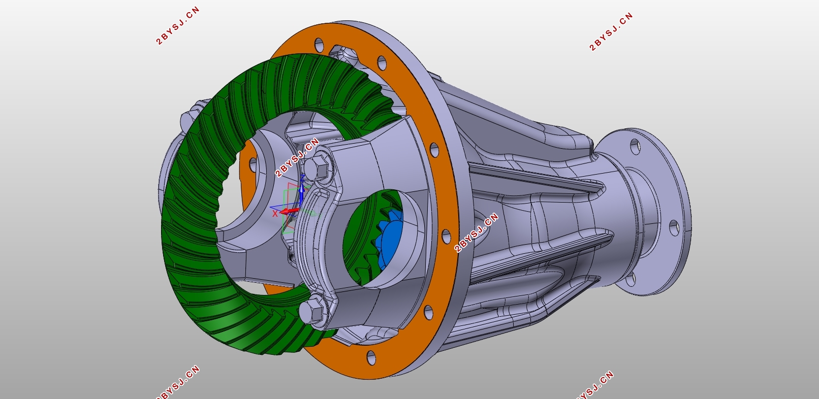
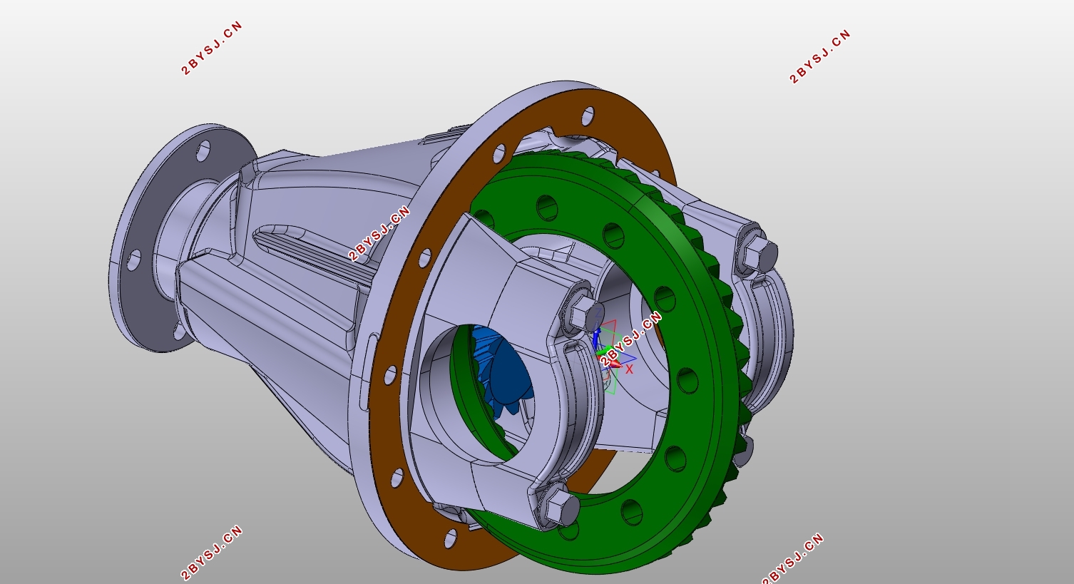
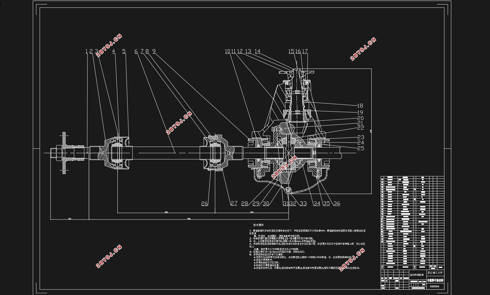
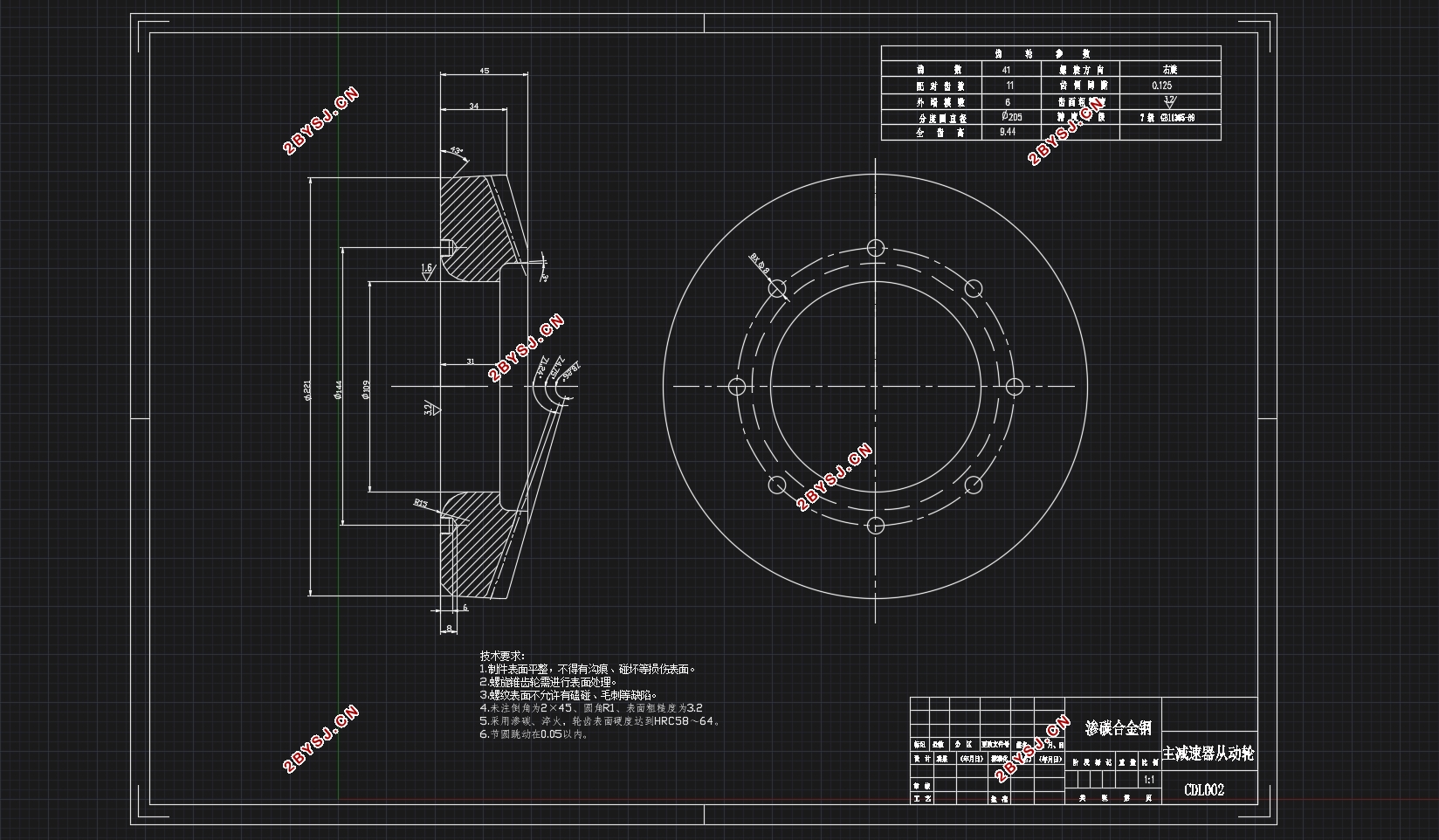
论文主要是自己针对东风英菲尼迪Q50L这款车型的驱动桥进行了自主的一个设计,根据给定的车型相关参数,首先对主减速器进行设计,主要是对主减速器的齿轮进行校核并且对其几何尺寸进行设计,本文选定设计单级主减速器,在齿轮形式螺旋锥齿轮、双曲面齿轮、圆柱齿轮和蜗轮蜗杆中本文选择的是螺旋锥齿轮。而后对于差速器的形式,在普通对称式圆锥行星齿轮差速器和防滑差速器两种中本文选择的是普通对称式圆锥行星齿轮。最后,本文对于半轴和桥壳采用了全浮式半轴和整体式桥壳。并用CATIA绘制了驱动桥的三维图并将其转化为二维图纸。
关键词:驱动桥;主减速器;差速器;CATIA
Abstract
Nowadays, with the rapid development of economy and society, the development of the automobile industry is also at high speed, the automobile technology is also on the high-speed train, the corresponding car-driven bridge technology is also progressing, the continuous emergence of new technology, Its production is also moving in the "three" aspects of the constantly close.
The paper is mainly for the Dongfeng Infiniti Q50L this model of the drive axle of a design, according to a given vehicle-related parameters, the first design of the main reducer, mainly on the main reducer gear check and The geometric dimensions of the design, this paper selected the design of single-stage main reducer, in the form of helical bevel gears, double-surface gears, cylindrical gears and worm gear in this paper is selected spiral bevel gear. And then for the form of differential, in the ordinary symmetrical cone planetary gear differential and non-slip differential in this paper is the choice of ordinary symmetrical cone planetary gears. Finally, this paper uses a full-floating axle and a monolithic axle housing for the axle and axle housing. And using CATIA to draw the three-dimensional image of the drive axle and convert it into two-dimensional drawings
Key Words:drive axle;the main reducer;differential;CATIA

目录
第1章 绪论 1
1.1 概述 1
1.2 驱动桥设计的现状及分析 1
1.3 驱动桥设计的基本要求 1
第2章 主减速器设计 3
2.1 主减速器的结构型式 3
2.1.1 主减速器齿轮的类型选择 3
2.1.2 主减速器主动锥齿轮的支撑形式及安装方法 3
2.1.3 主减速器从动锥齿轮的支撑形式及安置方法 4
2.1.4 主减速器的减速型式 5
2.2 主减速器的基本参数的选择与设计计算 5
2.2.1 主减速比的确定 5
2.2.2 车型变速器传动比的确定 5
2.2.3 主减速器计算载荷的确定 6
2.2.4 主减速器齿轮基本参数的选择 7
2.2.5 主减速器锥齿轮强度计算 9
2.2.6 主减速器锥齿轮材料的选择 10
2.2.7 主减速器轴承的计算 11
2.2.8 主减速器的润滑 14
第3章 差速器的设计计算 16
3.1 差速器结构型式的选择 16
3.2 普通锥齿轮差速器的设计 16
3.2.1 普通锥齿轮差速器齿轮的设计 16
3.2.2 差速器齿轮强度的计算 18
3.3 差速器齿轮材料的选择 18
第4章 车轮传动装置的设计 19
4.1 半轴的型式 19
4.2 半轴的载荷计算及材料 20
4.3 球笼式万向节的设计计算 21
4.4 万向节材料的选择 22
第5章 驱动桥壳的设计计算 23
5.1 驱动桥结构型式的选择 23
5.2 驱动桥壳强度计算 24
第6章结论 27
参考文献 28
致谢 29
