玩具机器人手臂的注塑的模具设计(含CAD零件图装配图,UG三维图)
无需注册登录,支付后按照提示操作即可获取该资料.
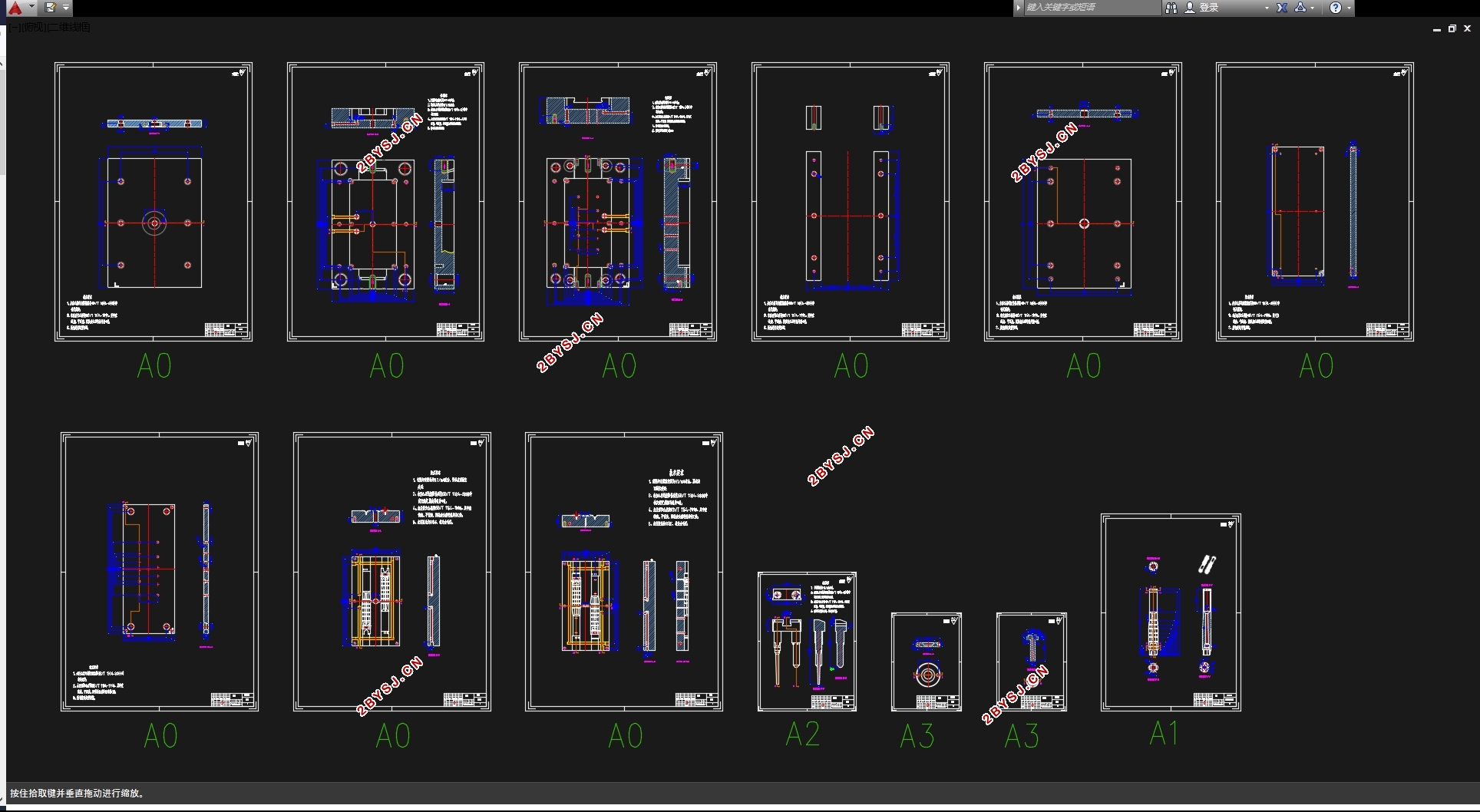
玩具机器人手臂的注塑的模具设计(含CAD零件图装配图,UG三维图)(设计说明书16000字,CAD图13张,UG三维图)
摘 要
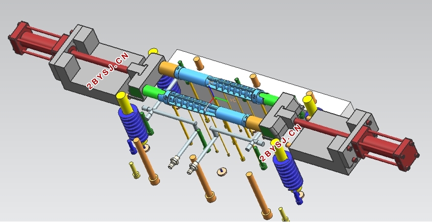
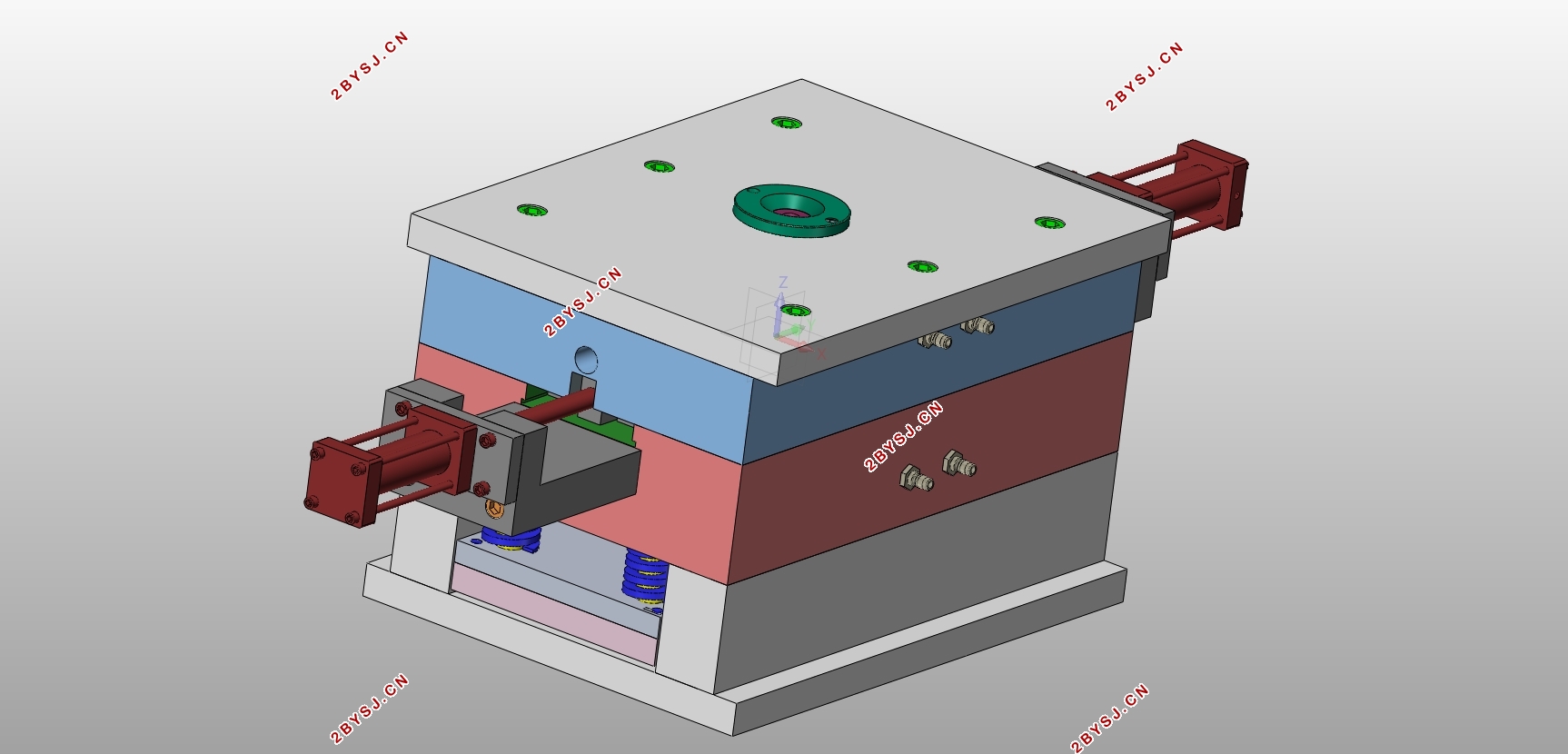
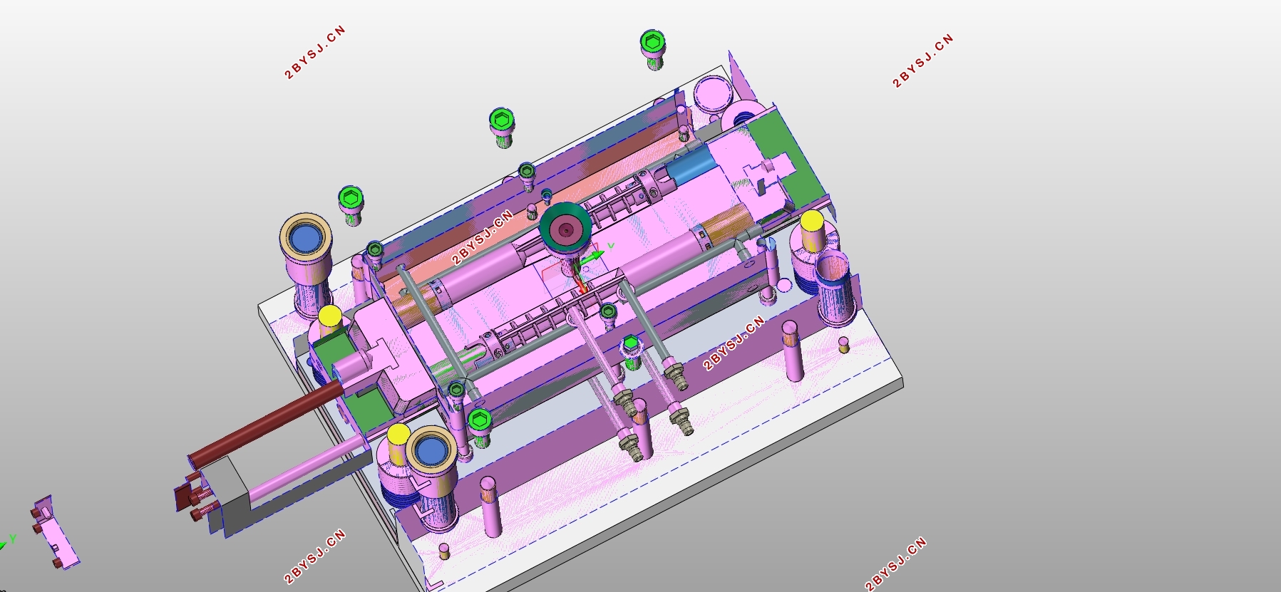
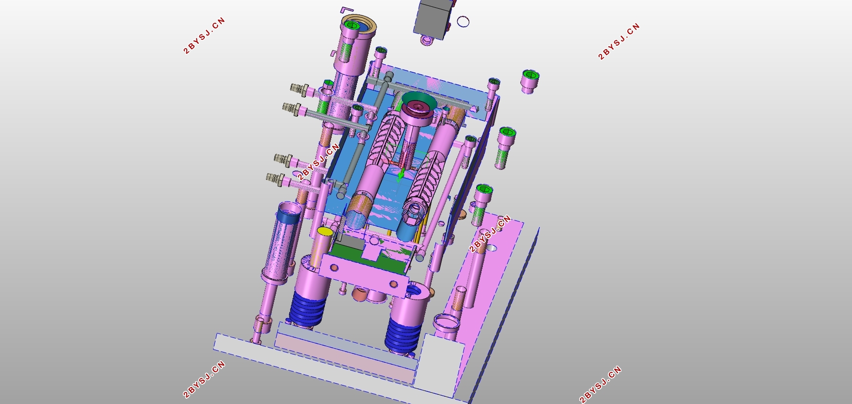
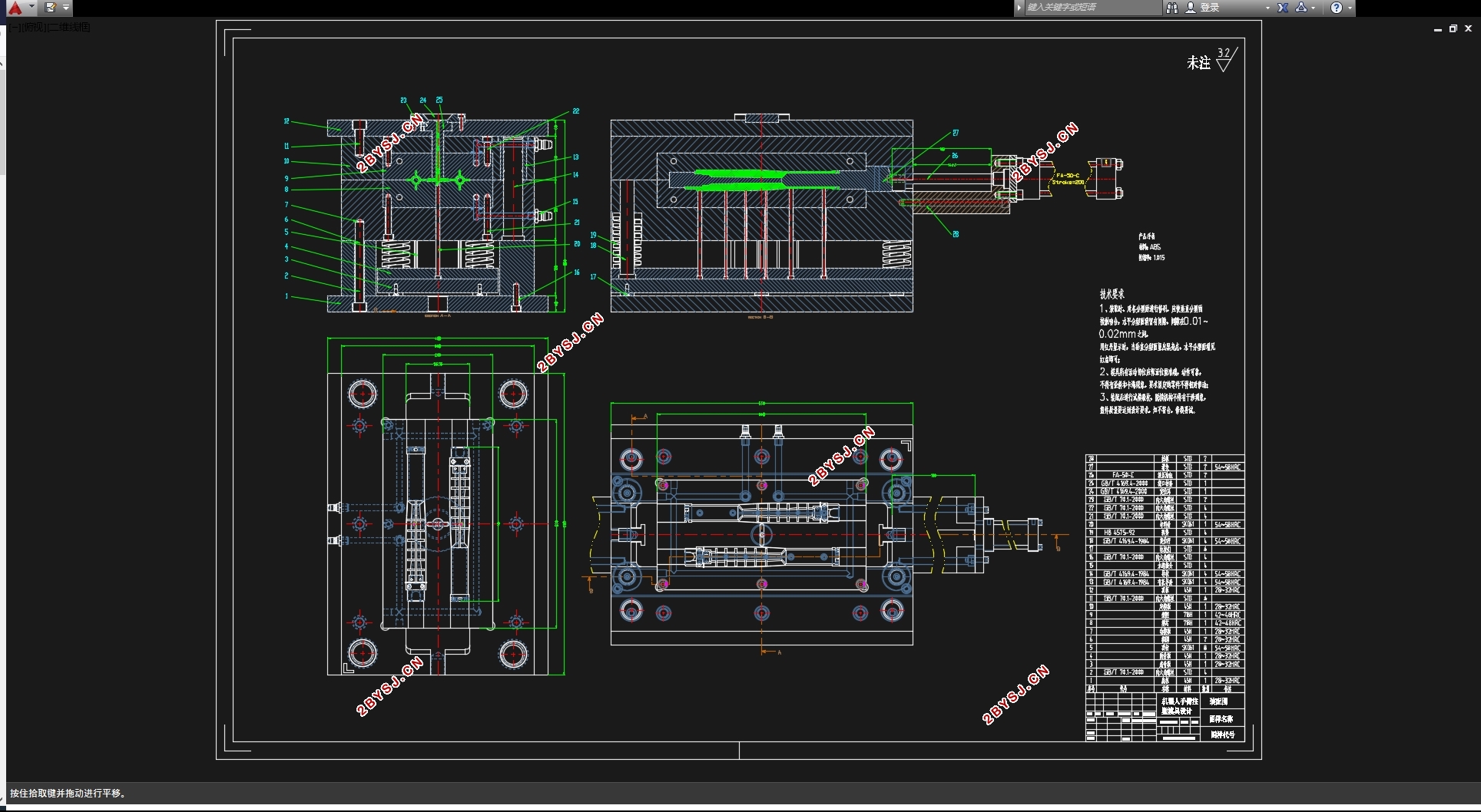
本课题玩具机器人手臂的注塑的模具设计,通过对产品的结构了解,然后分析其特征设计出一副结构合理的注塑模。主要从模模具的浇注系统、成型部分、顶出、冷却等方面入手设计。在设计时主要采用了应用UG软件对玩具机器人手臂制品进行了零件造型;使用CAD及其燕秀工具箱对玩具机器人手臂进行模具设计。主要完成了对玩具机器人手臂的产品的模具的结构的设计;设计过程中需要对塑件进行一个详细的计算;分析模具的各种机构,比如冷却顶出流道还有模架的选择等方面,按照自己设计好的结构画出注塑模具的总装配图。在分析好模具的机构时发现由于塑件外侧壁有倒扣,正常无法脱模,所以需要采用侧抽芯机构,分析产品的结构发现这个塑件比较适合是采用侧浇口进浇。然后顶出机构选择推杆顶出比较合适,这也是模具当真比较实用也比较经济的一种做法,模架选择的是标准的模架,最终完整的设计模具的细节和设计出详细的模具零件图。
关键字:玩具机器人手臂,注塑模,UG,滑块
Abstract
In this paper, the mold design of the robot arm injection molding, by understanding the structure of the product, and then analyze the characteristics of the design of a reasonable structure of injection molding mold. Mainly from the mold pouring system, forming part, top out, cooling and other aspects of the design. At the time of design, UG software was used to model the arm products of toy robot. The die design of robot arm was carried out by using CAD and its Yanxiu tool box. It mainly completes the design of the die structure of the product of the toy robot arm; The design process needs to carry out a detailed calculation of the plastic parts; Analyze the various mechanism of mould, such as cooling the top outlet channel and the selection of die frame, draw the assembly diagram of injection mould according to the structure designed by oneself. When analyzing the mechanism of the mold, it was found that due to the inverted buckle on the outer wall of the plastic part, it was normal to be unable to demoulding. Therefore, it is necessary to use the side core mechanism. Analyzing the structure of the product, it was found that this plastic piece is more suitable for the use of side casting.
Key: Mini Umbrella, injection mold, UG, slider

目 录
第1章 绪论 1
1.1 引言 1
1.2 模具的发展 1
1.3 本设计研究的主要内容 2
1.4 毕业设计的意义 2
第二章 塑件工艺性分析 3
2.1 塑件形状 3
2.2 ABS材料分析 3
2.3 塑料成型工艺性能分析 3
2.4 塑件尺寸精度分析 4
2.5 结构工艺性分析 4
第三章 注塑机的选择 6
3.1 注射机的分类 6
3.2 注塑机类型的选用以及相关参数的校核 6
3.2.1 估算塑件体积 6
3.3.2锁模力的计算 7
3.3.3 注塑机型号的选择 7
3.3.4 注射机相关参数的校核 7
第四章 模具基本结构的确定 9
4.1 分型面的选择与排气系统的设计 9
4.1.1 分型面的选择 9
4.1.2 排气糟的设计 9
4.2 塑件成型方案的确定 10
4.2.1 型腔数目的对比 10
4.2.2 脱模机构的对比 10
4.2.3 两大浇注系统的对比 10
4.2.4 方案的确定 11
4.3 模具腔数的确定 11
第五章 浇注系统的设计 12
6.1 确定浇口位置 12
5.2 主流道的设计 12
5.3分流道的设计 13
5.4冷料穴的设计 14
第六章 主要结构的设计 14
6.1 成型零部件设计 14
6.1.1 型腔径向尺寸 14
6.1.2 型腔深度 15
6.1.3 型芯径向尺寸 15
6.1.4 型芯高度 16
6.1.5 型腔的设计 16
6.1.6 型芯的设计 17
6.2模架的选用 17
6.2.1 选购标准模架的优点 17
6.2.2 模架的选择 18
6.2.3 模架与注射机相关参数的校核 19
6.3 导向机构的设计 20
6.4温度调节系统的设计 21
6.5模具的装配 23
6.6 模具动作过程 23
结 论 25
参考文献 26
谢 辞 27
