简易升降机械手设计及三维建模(含CAD图,SolidWorks三维图)
无需注册登录,支付后按照提示操作即可获取该资料.
简易升降机械手设计及三维建模(含CAD图,SolidWorks三维图)(任务书,开题报告,外文翻译,论文说明书14700字,CAD图3张,SolidWorks三维图)
摘要
本文利用三维建模软件SOLIDWORKS和有限元分析软件ANSYS设计并校验了所设计的新型桥梁检测车。虽然传统的桥梁检测车也能完成桥下作业,但是对于桥面以上范围作业不能一机两用。研发新型桥梁检测车的具有重要的作用。由于新型桥梁检测车能一机两用,使得单一设备的成本上升,但是总成本大大降低,相比传统的桥梁检测车,更能响应市场的需要。对桥梁检测车的进一步优化设计,将对于国家检测机械的开发做出巨大贡献。
论文主要研究了桥梁检测车的结构形式、驱动方式、传动方式、工作过程。设计并验算了主桁架、检测桁架以及回转机构的承载能力。
研究结果表明:本次设计的桥梁检测车与传统的设备相比功能更全面,作业范围更广,发展空间更大。从对主桁架和检测桁架的受力验算分析可以确定所设计的结构参数合理,从ANSYS分析结果可以得出检测桁架的承载能力足够,但主桁架需要增加一定数量的筋板,以是得其安全性得到保障
关键词:桥梁检测车;回转支承;力学校验;ANSYS;SOLIDWORKS
Abstract
In this paper, we use the 3d modeling software SOLIDWORKS and finite element analysis software ANSYS to design and verify the New Bridge Inspection Vehicle that we designed.Even if traditional vehicle can also inspect damage below the bridge, it’s not able to inspect impairment abovethe bridge by using only one machine. It is important to design a new kind of inspection vehicle. Because of the function of the new vehicle, the cost of one machine increases, however the total payment reduced. Compared to the traditional vehicle, it will suit the market and well sold. Further research and design on bridge inspection vehicle would make great contribution to the development of other inspection equipment.
This paper mainly studies the form of the structural, driving mode, transmission mode and the working process of the New Bridge Inspection Vehicle. The bearing, main truss and inspection truss are designed and checked.
The results shows that compared to the traditional machine, the New Bridge Inspection Vehicle has more comprehensive function, wider operation range and larger development size. According to the checking of analysis of the main truss and the inspection truss, it’s obvious that the parameters of the New Bridge Inspection Vehicle are suitable. After analysis ANSYS’s result, we can find that the bearing capacity of the trusses is sufficient, but the main truss needs to add some stiffeners to ensure the safety
Key Words:Bridge inspection vehicle;Slewing bearing;Mechanics check;ANSYS;SOLIDWORKS
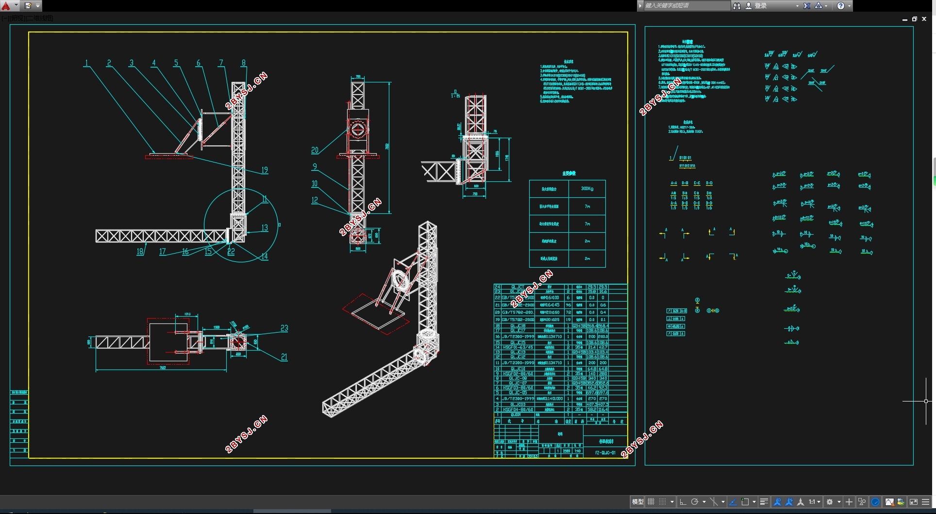
检测车结构设计参数
根据设计要求,起升高度为6m,最大外载荷≤4T,回转角度360°。初步选定以下基本参数:
表2.1 新型桥梁检测车参数
检测臂长度 7m 跨越人行道宽度 1.5m
检测平台宽度 0.6m 主桁架最大下降深度 5m
跨越护栏高度 1.5m 检测臂回转范围 0~360°
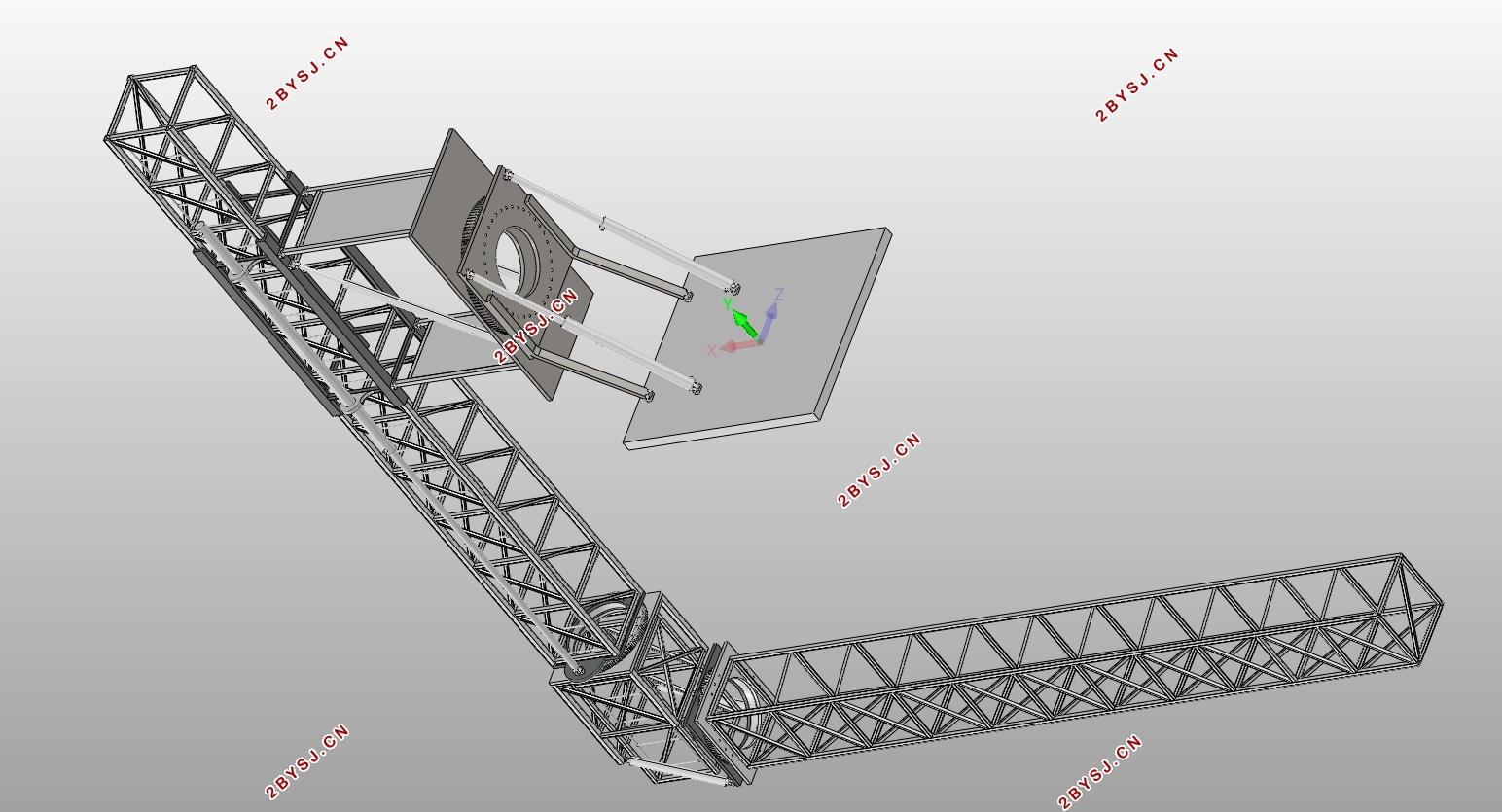
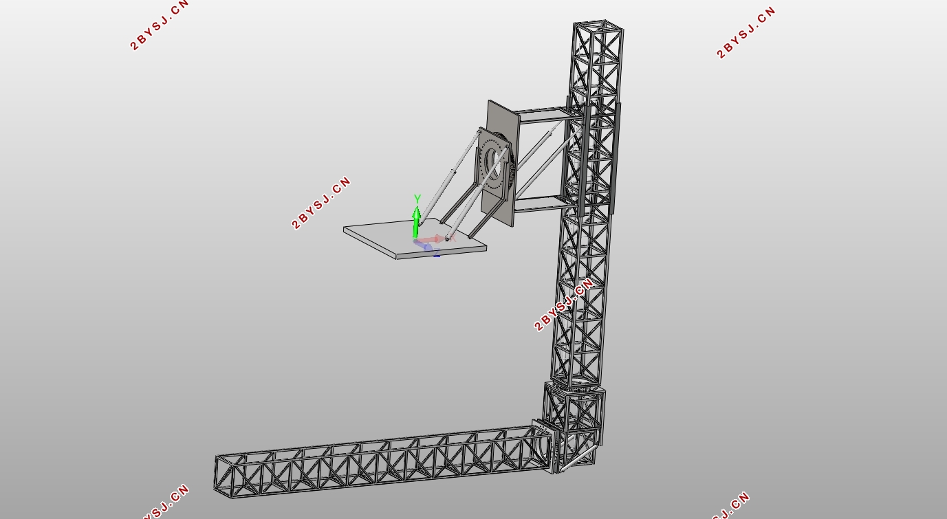
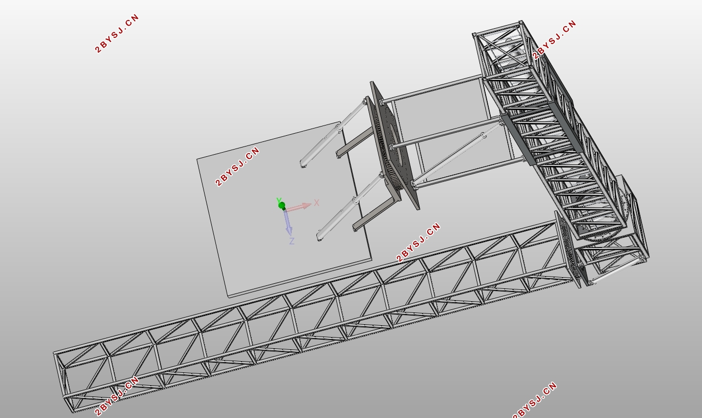
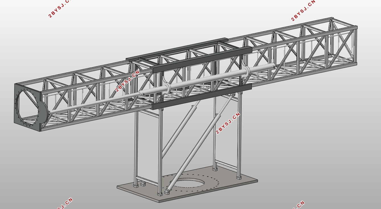


目录
第1章绪论 1
1.1 课题研究背景 1
1.2 国内外研究现状 2
1.2.1 国内研究现状 2
1.2.2 国外研究现状 2
1.3本文研究内容 4
第2章新型桥梁检测车臂架设计 5
2.1 新型桥梁检测车设计任务 5
2.2 检测车结构设计参数 5
2.3检测臂总体方案确定 5
2.3.1 检测臂的结构形式的确定 5
2.3.2 检测臂的材料选择 6
2.3.3 检测臂中各杆件的截面形状 7
2.4 新型桥梁检测车的臂架组成及其展开过程 8
2.4.1 新型桥梁检测车的臂架组成 8
2.4.2 桥梁检测车工作时臂架展开过程 8
2.5 桁架结构设计 11
2.5.1 主桁架结构设计 11
2.5.2 检测桁架结构设计 11
2.6回转机构设计 12
2.6.1 回转机构驱动方式确定 12
2.6.2 回转机构传动方式确定 12
2.6.3 回转支承的选择 12
本章小结 13
第3章回转机构受力分析 14
3.1 回转机构Ⅰ受力分析 14
3.1.1 回转机构Ⅰ外载荷分析 14
3.1.2 回转机构Ⅰ齿轮圆周力分析 17
3.2 回转机构Ⅱ受力分析 17
3.2.1 回转机构Ⅱ外载荷分析 17
3.2.2 回转机构Ⅱ齿轮圆周力分析 18
3.3 回转机构Ⅲ受力分析 20
3.3.1 回转机构Ⅲ外载荷分析 20
3.3.2 回转机构Ⅲ齿轮圆周力分析 21
本章小结 22
第4章新型桥梁检测车液压系统分析 23
4.1 桥梁检测车液压传动系统设计要求 23
4.2 液压系统回路设计 23
4.2.1 回转机构液压回路设计 23
4.2.2 液压缸回路设计 24
4.3 液压执行元件分析 25
4.3.1 液压马达参数计算 25
4.3.2 液压缸参数计算 26
本章小结 27
第5章桥梁检测车桁架结构受力分析 28
5.1 检测桁架受力分析 28
5.1.1 当检测桁架处于竖直时受力分析 28
5.1.2 当臂架完全展开时受力分析 29
5.2 主桁架受力分析 30
本章小结 31
第6章桁架结构有限元分析 33
6.1 有限元软件ANSYS简介 33
6.2 检测桁架有限元分析 33
6.3 主桁架有限元分析 35
本章小结 36
第7章经济性和环保性分析 37
7.1 经济性分析 37
7.2 环保性分析 38
本章小结 38
第8章总结与展望 39
8.1 全文总结 39
8.2 未来展望 39
参考文献 41
致谢 42
