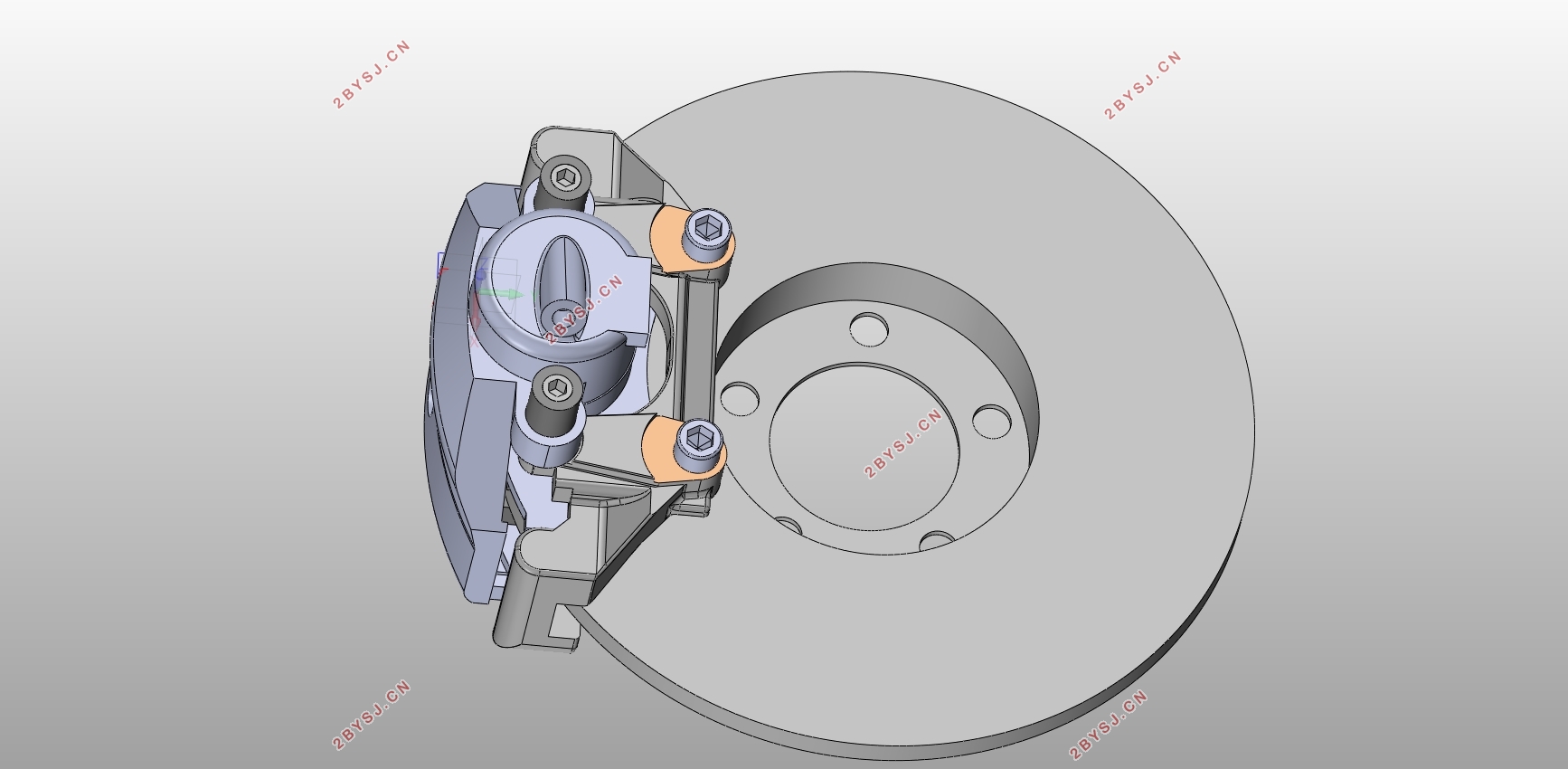
纯电动汽车制动系统设计(含CAD零件装配图,SolidWorks三维图)(英文版)
无需注册登录,支付后按照提示操作即可获取该资料.
纯电动汽车制动系统设计(含CAD零件装配图,SolidWorks三维图)(英文版)(任务书,开题报告英文版,文献摘要,外文翻译,论文说明书英文版11000字,CAD图纸11张,SolidWorks三维图)
Abstract
The car was born because of its speed, but the car often encounters complex and variable road conditions during driving, such as entering curves, uneven roads, two-car intersections, and sudden obstacles. In order to ensure the safety of driving, the car is required to Decelerate or even stop in the shortest distance. As one of the four major systems of the automobile chassis, the braking system can effectively control the speed of the vehicle and is an active guarantee for the safety of the vehicle.[1]
The brake is an important part of the braking system. This paper mainly introduces the brake design of the passenger car. Starting from the comparison of the structure and performance of disc type and drum brakes, disc brakes have become the mainstream of current brake systems due to the increasing performance and driving speed of vehicles, in order to increase the braking performance of vehicles at high speeds. Since the disc brake disc is exposed to air, the disc brake has excellent heat dissipation. When the vehicle is in emergency braking at a high speed, the braking performance is less likely to decline, and the vehicle can obtain the best braking effect to improve the driving safety of the vehicle. In addition, due to the rapid response of disc brakes, high-frequency braking actions can be completed. Therefore, modern passenger cars mostly use braking schemes that are used with ABS systems, ESP systems, and disc brakes to meet the requirements of rapid braking. [2]
Taking into account the above advantages of disc brakes, and the overall performance of the referenced models is better, which belongs to mid-to-high grade passenger vehicles. Therefore, this design has adopted floating disc brakes for front and rear wheels, ventilated discs for front wheels and discs for rear wheels. brake.[3]
After the basic form of the brake is selected, the following design of the brake is developed in this paper. 1. Parameters of braking system: including the selection and calculation of braking force distribution coefficient, synchronous adhesion coefficient, braking strength, adhesion coefficient utilization rate and maximum braking torque; 2. Brakes and their components: brake discs, system The size calculation and material selection of the brake parts such as movable caliper body and friction pad, etc. 3. Parking brake: The rear parking brake is selected for this design, and the parking brake is installed on the rear wheel brake. The mechanical structure; Fourth, the brake drive mechanism: brake wheel cylinder, brake master cylinder, and pedal stroke design calculations.
After the above design is completed, the braking deceleration and braking distance of the designed brake are calculated, and the front and rear axle braking force distribution curves are drawn using MATLAB programming. After the above requirements are met, the rationality of the brake design is verified. . Finally, the three-dimensional model of the brake caliper body, brake disc, piston, and friction pad of the vehicle brake was designed and designed using solid works.[4]
Keywords:EV;braking system;disc brake;SOLID WORKS;MATLAB
Num. Name Symbol
Value
Unit
1 mass m_0 1680.00 kg
2 Height of mass center 〖hg〗_o 770.00 mm
3 Wheel base L 2660.00 mm
4 The distance frommass center to the front axle A_0 1280.00 mm
5 The distance
from mass center of to the rear axle B_█(0@) 1380.00 mm
6 Front axle load G_01 1008.00 kg
7 rear axle load G_█(02@) 672.00 kg


Contents
Abstract III
1.Introduction 1
1.1 Basic concept of braking system 1
1.1.1 The composition of the braking system 1
1.1.2 Type of braking system 1
1.2 Research status of braking system 2
1.3 Main content of the project 4
1.4 Project research scheme 7
2.The choice of brake form 8
2.1 Introduction of drum brakes 8
2.2 Introduction of disc brakes 9
2.3 Selection of brake structures 10
3.Main parameters and selection of brake 11
3.1 Determination of main parameters of disc brake 11
3.1.1 Brake disc diameter D 11
3.1.2 Thickness of brake disc h 11
3.1.3 Inside and outside radius of friction linerR1,R2 12
3.1.4 Working area of brake liner A 12
4.Structural design of main parts of disc brake 13
4.1 brake disc 13
4.2 Brake caliper 13
4.3 Brake slipper 14
4.4 Friction material 15
5. Design and calculation of main parameters of brake 16
5.1 Determination of synchronous adhesion coefficient 18
5.2 Normal reaction of ground to front and rear wheels 19
5.3 Determination of the distribution coefficient β of braking force 20
5.4 Determination of braking moment for front and rear brakes 20
5.5 Braking torque required for emergency brake and parking brake 21
5.5.1 Emergency brake 21
5.5.2 Parking brake 21
5.5.3 Calculation of wear characteristics of linings 22
6.Structural form selection and design calculation of brake drive mechanism 24
6.1 Choice of structure form of braking drive mechanism 24
6.2 Multi-loop system for braking pipeline 26
6.3 Design and calculation of hydraulic braking drive mechanism 28
6.3.1 Determination of the diameter of the brake wheel cylinder 29
6.3.2 Determination of the diameter of the main brake cylinder 29
6.3.3 Braking pedal force and pedal stroke 30
6.3.4 Design and calculation of vacuum booster 31
7.Brake performance analysis 32
7.1 Braking performance Evaluation Index 32
7.2 braking efficiency 32
7.2.1 braking deceleration α 32
7.2.2 braking distance S 33
7.3 The constant braking performance 33
7.4 The direction stability of the vehicle during braking 33
7.5 Analysis of braking force distribution curve 34
Conclusion 36
Reference 37
Acknowledgements 38
Appendix A Brake 3D modeling 39
Appendix B Exploded view 45
Appendix C MATLAB programming 46
Appendix D EXCEL calculation 47
