智能车自主转向系统设计(含CAD图,SolidWorks三维图)
无需注册登录,支付后按照提示操作即可获取该资料.
智能车自主转向系统设计(含CAD图,SolidWorks三维图)(任务书,开题报告,文献摘要,外文翻译,论文说明书13000字,CAD图纸5张,SolidWorks三维图)
摘 要
汽车行驶过程中,并不只有直线行驶这一种情况,经常需要改变车辆行驶方向,正是基于这样的驾驶需求而设立专门的转向系统,以达到使车轮相对于汽车纵轴线偏转一定角度的目的。
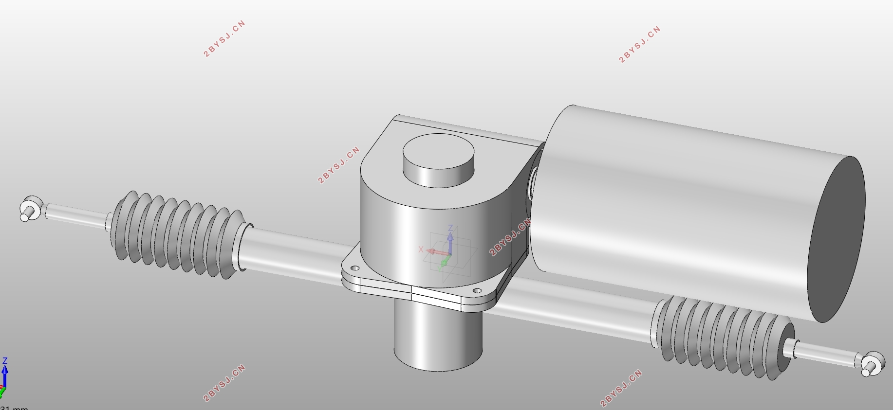
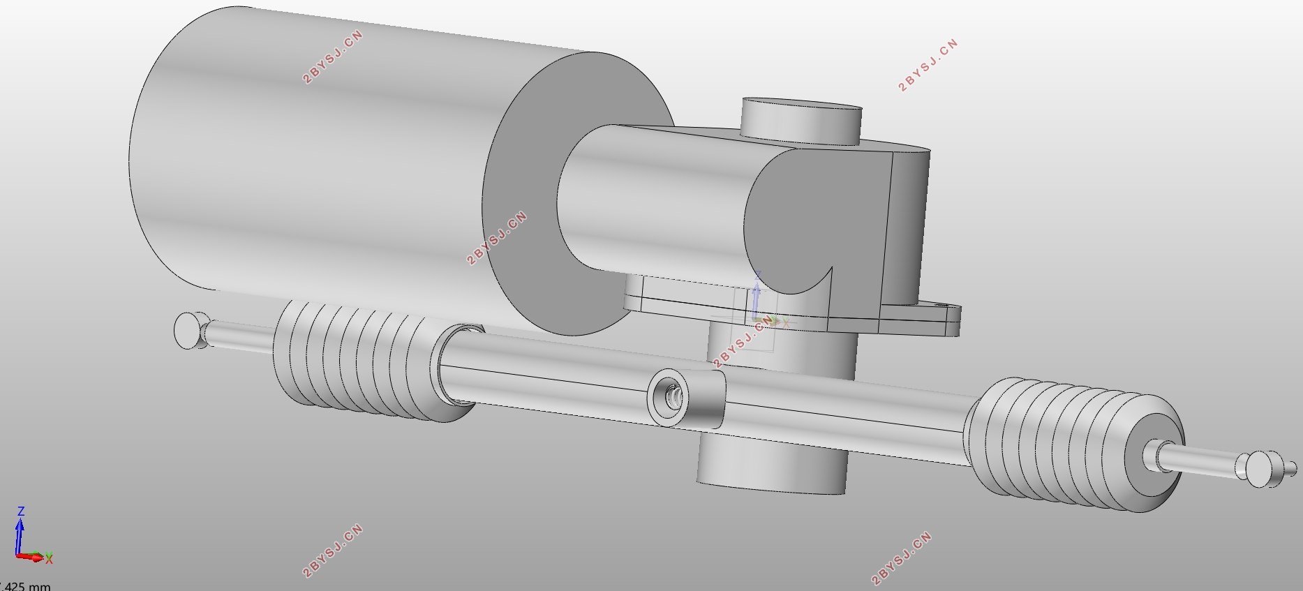
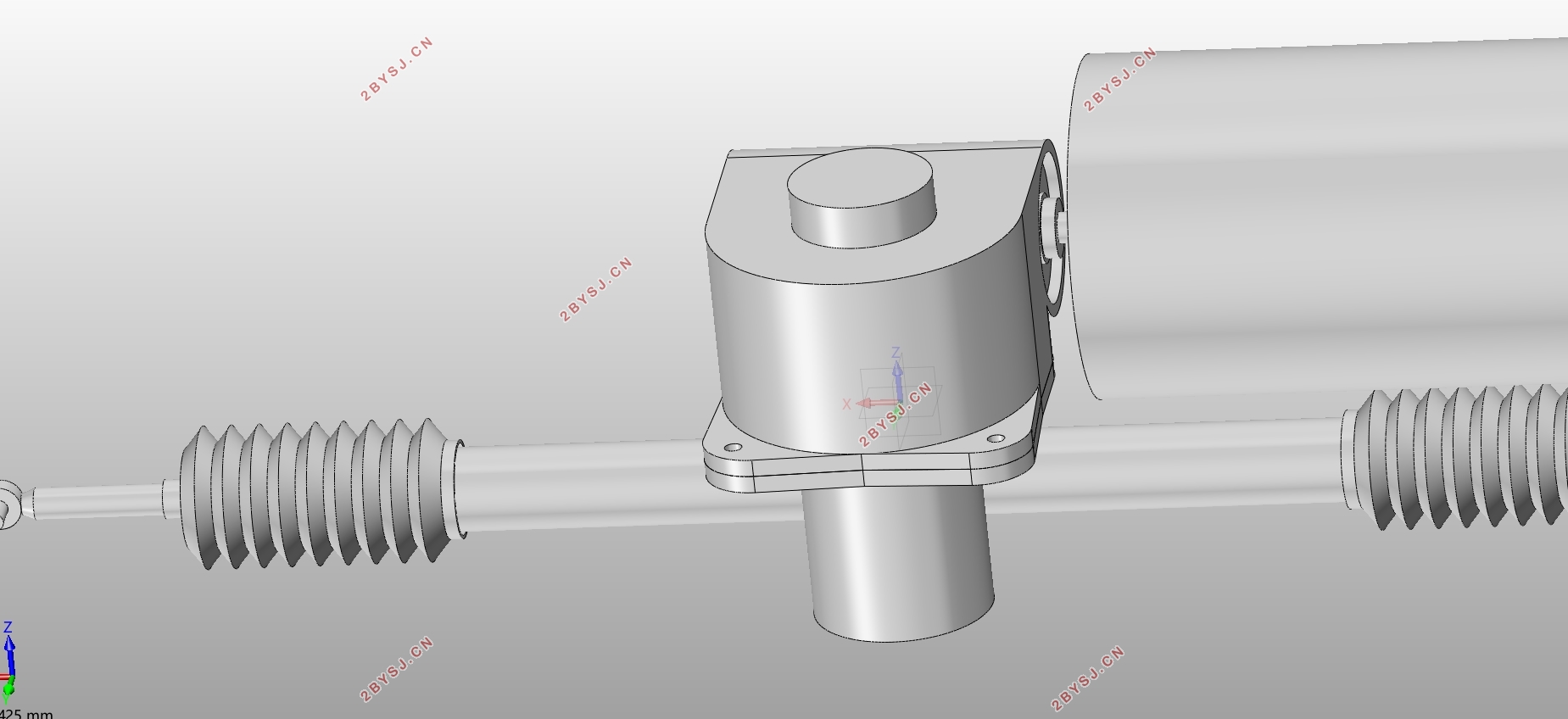
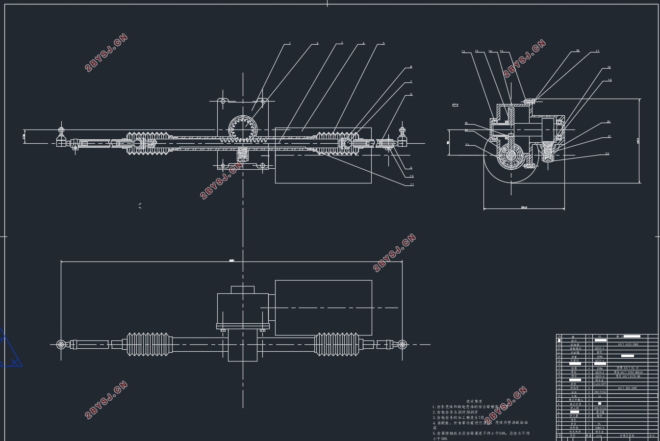
齿轮齿条式和循环球式转向器是当前主流的两种转向器,其中,齿轮齿条式更多地应用于中小型车。智能车自主转向系统的设计,参照了双小齿轮式电动助力转向系统的部分结构,可以实现在没有驾驶员介入的情况下,转向系统在电机的驱动下实现转向功能。
本文以英菲尼迪Q50车型的转向系统为研究对象,设计的主要内容是:首先了解了本课题研究的目的和意义及研究现状,通过查找书籍及文献去了解转向系统的具体结构及原理,完成了转向系统中的构件的参数设计。了解了各种不同的电动助力转向的形式,并在此基础上想办法去掉转向操纵机构,完全由电机来驱动转向系统。利用Matlab和Adams进行了转向梯形的优化设计。
关键词:转向系统;智能;优化设计
Abstract
A car not only drives by a straight line, and it is necessary to change the driving direction. It is just based on this demand that a special steering system is established to achieve a certain degree of deflection of the wheel,and the degree is relative to the longitudinal axis of the vehicle.
Rack and pinion type and recirculating ball type steering gears are two kinds of mainstream steering gears, among which the rack and pinion type is more applicable to small and medium-sized vehicles. The design of the autonomous steering system of the smart car refers to the structure of the double pinion type electric power steering system, and the design can achieve the steering function under the driving of the electric motor, without driver’s intervention.
This article takes the steering system of the Infiniti Q50 as research object. The main contents of the design are: firstly understanding the purpose, significance and research state, and finding out the specific structure and principle of the steering system by searching for books and literatures,completing the design of the parameters of the components in the steering system. After understanding a various forms of electric power steering, on this basis, I find a way to remove the steering operating mechanism, making steering system completely driven by the motor . The optimal design of the steering trapezoid is performed using Matlab and Adams.
Key words: Steering system; Intelligence;Optimal design
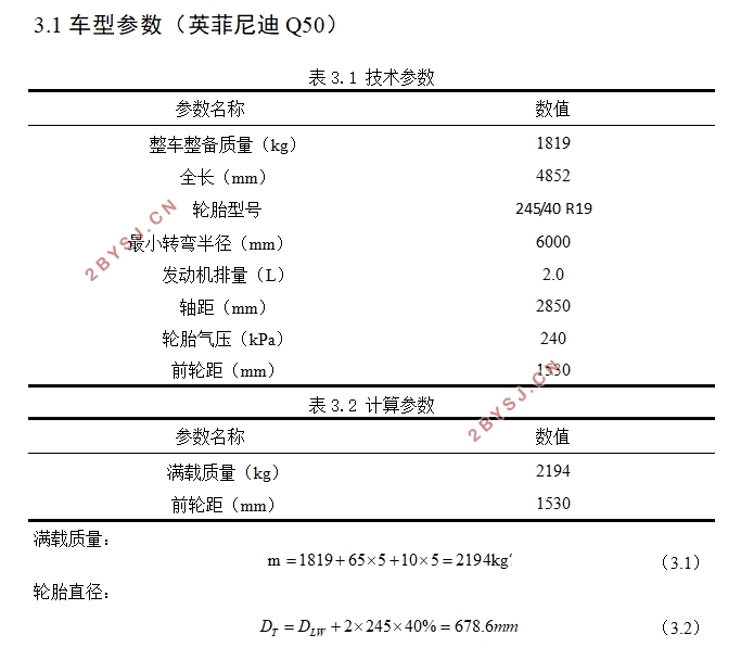
3.1车型参数(英菲尼迪Q50)
表3.1 技术参数
参数名称 数值
整车整备质量(kg) 1819
全长(mm) 4852
轮胎型号 245/40 R19
最小转弯半径(mm) 6000
发动机排量(L) 2.0
轴距(mm) 2850
轮胎气压(kPa) 240
前轮距(mm) 1530
表3.2 计算参数
参数名称 数值
满载质量(kg) 2194
前轮距(mm) 1530


目 录
第1章 绪论 1
1.1 研究意义和目的 1
1.2 研究现状 1
1.3 研究内容 2
第2章 无人驾驶 3
2.1 背景 3
2.2 关键技术 3
2.3自主转向原理 4
第3章 目标车型 6
3.1车型参数(英菲尼迪Q50) 6
3.2 车型定位 6
3.3 轴荷分配 7
3.4 转向系阻力计算 7
第4章 转向系统组成 9
4.1 转向操纵机构 9
4.2 转向器 9
4.3 转向传动机构 9
第5章 转向器设计 10
5.1 转向器选型 10
5.2 转向器的输出形式 10
5.3 转向器布置形式: 11
5.4 齿轮齿条设计 12
5.4.1 结构选择 12
5.4.2 材料及热处理工艺 12
5.4.3 内外轮最大转角 12
5.4.4 齿轮齿条参数计算 13
5.5转向器传动间隙 17
第6章 电机及减速机构 18
6.1 电机作用位置 18
6.2 电机选型 19
6.3 电机额定转矩 19
6.4 额定转速 20
6.5 功率 20
6.6 尺寸设计 20
6.7减速装置 21
第7章 转向传动机构设计 24
7.1 优化模型 24
7.1.1 目标函数 25
7.1.2设计变量 26
7.1.3 数学模型 26
7.1.4 MATLAB及ADAMS结果 27
7.2 转向横拉杆 28
7.3 选材及校核 28
结论 30
参考文献 31
附录 32
致谢 34
