某高级轿车电动助力转向系统设计(含CAD零件图装配图,CATIA三维图)
无需注册登录,支付后按照提示操作即可获取该资料.
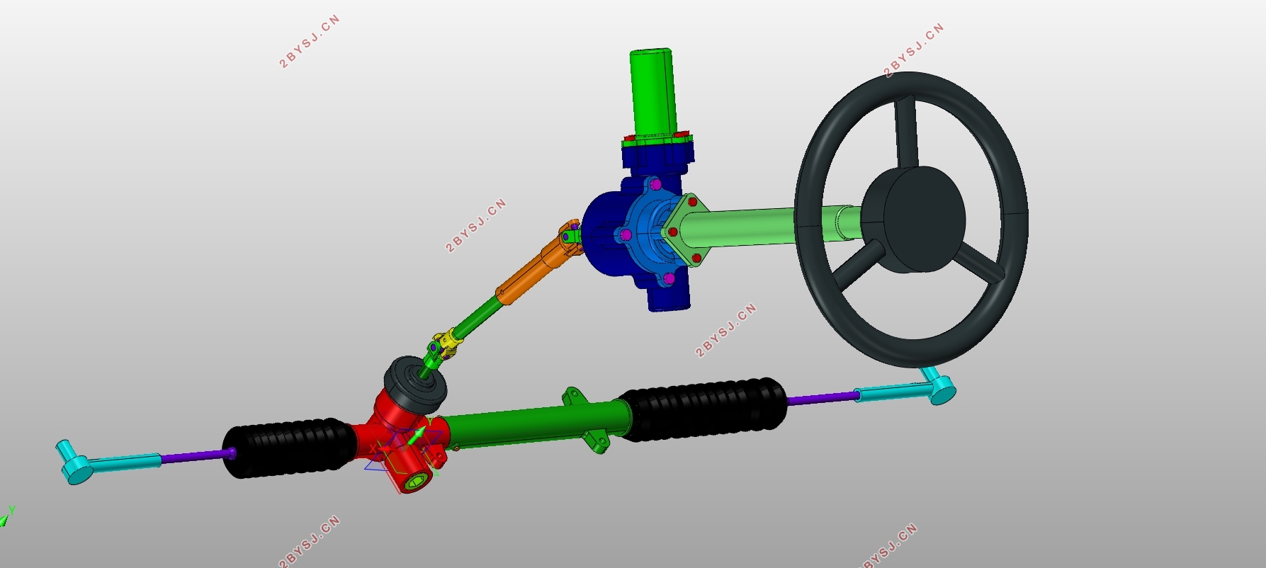
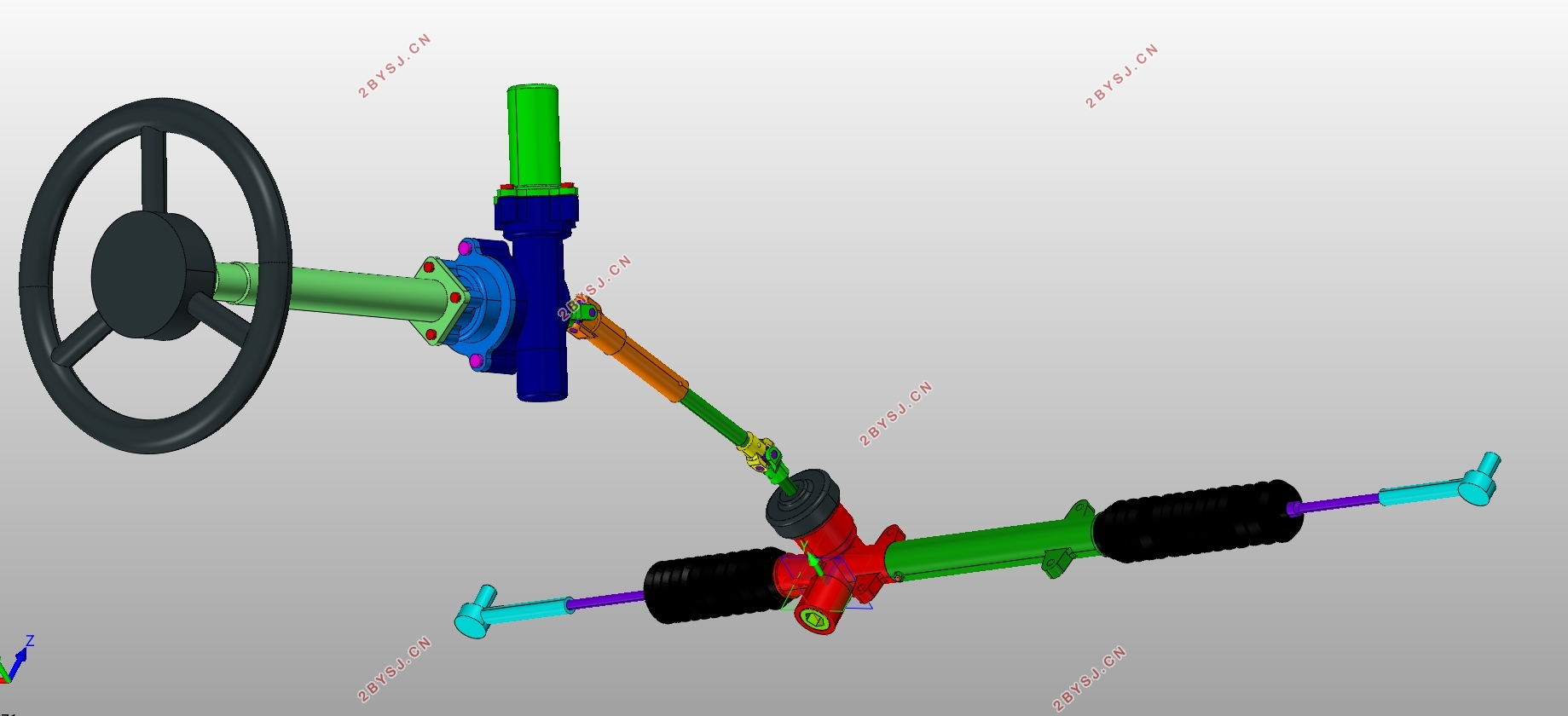
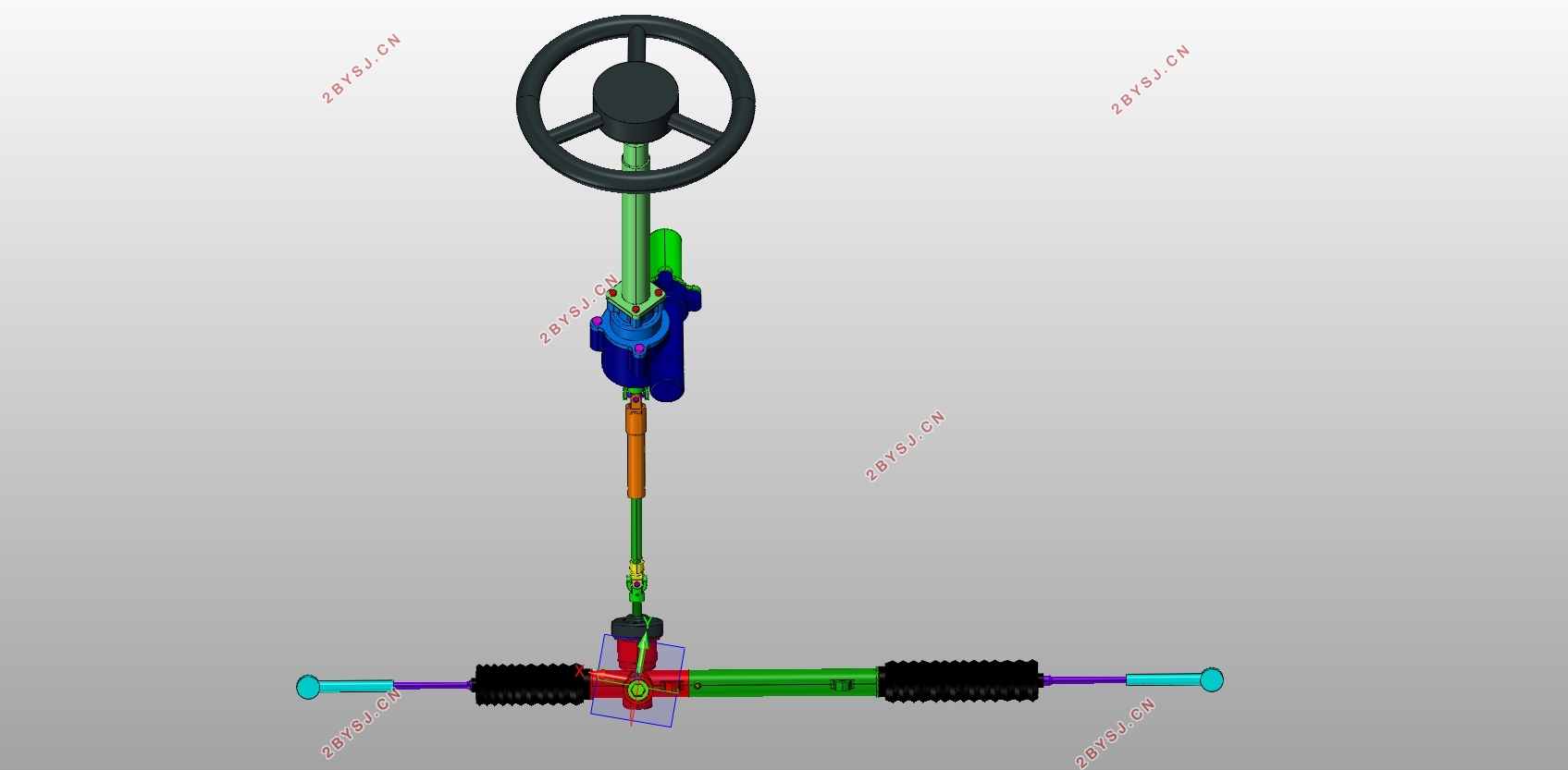
某高级轿车电动助力转向系统设计(含CAD零件图装配图,CATIA三维图)(任务书,开题报告,文献摘要,外文翻译,论文说明书10600字,CAD图6张,CATIA三维图)
摘要
随着汽车工业的发展,汽车产品的舒适性和安全性越来越受重视。汽车电动助力转向系统(Electric Power Steering System,简称为EPS系统)可以通过助力电机生成助力力矩,帮助驾驶人更轻便地完成转向操作,助力机构输出的力矩大小会随着车速的变化进行调整,确保驾驶人在低速时转向轻便,在高速时能保持路感。汽车行业一致认为EPS系统是转向系统发展的必然方向。
本文将对助力转向系统的发展历史做一个梳理,对EPS系统的分类、结构、功能、原理进行深入分析,之后将为参考车型设计电动助力转向系统。本文通过数学计算完成了转向系统主要参数性能、齿轮齿条转向器、蜗轮蜗杆减速机构、电机选型等设计工作。
汽车碰撞安全性正在越来越受人们的重视,在许多碰撞事故中,转向系统对驾驶人造成了较大的伤害。本文将介绍提高电动助力转向系统吸能性的不同设计方法,通过CATIA软件建立起EPS系统的三维模型,配合ANSYS软件的有限元分析功能,为EPS系统设计合理可行的吸能方案,提升转向系统的吸能性。
关键词:EPS系统;吸能性;有限元分析。
Abstract
With the development of the automotive industry, the comfort and safety of automotive products have become more and more important. The Electric Power Steering System (EPS system) can generate assist torques with the help of motor generators to help the driver complete the steering operation more easily. The torque output from the booster mechanism will be adjusted as the speed of the vehicle changes to ensure that the driver can operate steering easily at a low speed, and keep the road feeling at high speed. The automotive industry is unanimous that the EPS system is the inevitable direction of the development of the steering system.
This article will sort out the history of the power steering system and analyze the classification, structure, function and principle of the EPS system. After that, the electric power steering system will be designed for the reference model. In this paper, the calculation of the main parameters of the steering system, the rack and pinion gear, the worm and worm gear deceleration mechanism, and the motor selection are completed through mathematical calculations.
The safety of car crashes is getting more and more people's attention. In many collision accidents, the steering system caused a great deal of damage to the driver. This article will introduce different design methods for improving the energy-absorbing performance of electric power steering systems. The three-dimensional model of the EPS system will be established through CATIA software, and the finite element analysis function of ANSYS software will be used to design a reasonable and feasible energy-absorption scheme for the EPS system to improve the energy absorption of the steering system.
Key Words: EPS System; Energy absorption; Finite element analysis
本设计选择凯迪拉克XT5作为参考车型,参考车型采用前置前驱的驱动方案,助力类型采用电动助力方案,该车型的一些基本参数如表2-1所示。
表2-1 凯迪拉克XT5车型的基本参数
参数条目 参数值
发动机 2.0T 250马力 L4
最大功率(kw) 184
最大扭矩(N.m) 400
长*宽*高(mm) 4812*1903*1680
轴距(mm) 2857
最小离地间隙(mm) 185
最高车速(km/h) 210
轮距(mm) 1645
前轮胎规格 235/65 R18
后轮胎规格 235/65 R18


目录
摘要 1
Abstract II
第1章 绪论 1
1.1 助力转向系统的发展历史 1
1.2 汽车电动助力转向系统简介 2
1.2.1 电动助力转向系统的分类 2
1.2.2 电动助力转向系统的结构与工作原理 3
1.3 国内外的研究现状 3
1.4 EPS系统的优点 4
1.5 本文主要研究内容 4
第2章 转向系统的设计 5
2.1 转向系统主要性能参数 5
2.1.1 计算原地转向阻力矩 5
2.1.2 转向器力传动比与角传动比的计算 6
2.1.3 转向器的效率 6
2.2 齿轮齿条转向器的设计计算 7
2.2.1 设计齿轮的主要尺寸 8
2.2.2 设计齿条的主要尺寸 8
2.2.3 确定主动齿轮轴的直径 9
2.3 齿轮齿条载荷的校核计算 9
2.3.1 确定齿轮齿条的许用应力 10
2.3.2 校核小齿轮的弯曲疲劳强度 10
2.3.3 校核小齿轮齿面的接触疲劳强度 11
2.4 转向梯形 12
2.5 本章小结 12
第3章 助力机构的设计计算 13
3.1 电机的选型 13
3.2 蜗轮蜗杆减速机构的设计 14
3.2.1 蜗杆的设计与计算 14
3.2.2 蜗轮的设计与计算 15
3.2.3 蜗轮的接触强度校核 15
3.2.4 蜗杆的刚度校核 16
3.3 本章小结 16
第4章 基于CATIA建立电动助力系统的三维模型 17
4.1 齿轮齿条转向器 17
4.2 蜗轮蜗杆减速器 17
4.3 装配模型 18
第5章 对转向系统吸能性进行有限元分析 19
5.1 转向系统吸能性简介 19
5.2 转向系统吸能方法分类 20
5.2.1 转向轴错位缓冲吸能 20
5.2.2 转向柱管发生塑性变形吸收能量 20
5.2.3 吸能式方向盘 21
5.3 基于ANSYS软件设计吸能式转向柱管 21
5.4 本章小结 23
第6章 结论 24
6.1 本文的研究内容 24
6.2 展望 24
参考文献 25
致谢 26
