大众高尔夫轿车制动系统(盘式制动器)设计(含CAD零件装配图,CATIA三维图)
无需注册登录,支付后按照提示操作即可获取该资料.
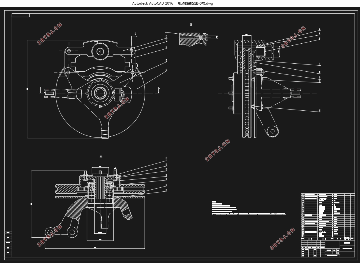
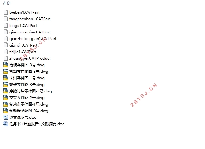
大众高尔夫轿车制动系统(盘式制动器)设计(含CAD零件装配图,CATIA三维图)(任务书,开题报告,文献摘要,论文说明书13900字,CAD图8张,CATIA三维图)
摘 要
本次设计主要针对大众高尔夫轿车进行了制动系统的设计,首先明确了本次设计的目的和意义,在了解了目前国内外制动系统的发展情况的前提下,确定了本次设计的基本思路,从制动器的选型、驱动机构的选型以及液压分路系统的选择入手,确定了本次设计所要采用的方案措施,然后通过查阅相关文献资料确定了汽车的基本参数,通过这些参数逐步设计出制动系统关键零件的主要参数,包括制动盘的尺寸,摩擦衬块的尺寸等。在设计完成后对所设计的制动系统进行校核并绘制制动系统的动力分配曲线,确保本次设计的合理性。最后对本次设计的制动盘进行CAE仿真分析,最大程度的保证设计的制动系统满足设计要求。
关键词:轿车;制动系统;盘式制动器;计算机辅助工程
Abstract
This design mainly focuses on the design of the braking system for the Volkswagen Golf (2018) sedan. Firstly, the purpose and significance of the design are clarified. Under the premise of understanding the development of the current domestic and foreign brake systems, the design has been confirmed. The basic idea of the secondary design, starting from the selection of the brake, the selection of the drive mechanism, and the selection of the hydraulic shunt system, determined the program measures to be adopted in this design, and then determined the basic parameters of the car by consulting relevant literature materials. Through these parameters, the main parameters of the key components of the braking system are gradually designed, including the size of the brake disc and the size of the friction pad. After the design is completed, the designed braking system is checked and the power distribution curve of the braking system is drawn to ensure the rationality of the design. Finally, the CAE simulation analysis of the brake disk designed this time ensures that the designed braking system meets the design requirements.
Key Words:car;Braking System;Disc brakes;Computer Aided Engineering (CAE)
整车及制动系统相关参数的选取和计算
本次设计所针对的车型是大众高尔夫(2018款1.6L手动时尚型)轿车,所以想要有针对性的完成设计任务,就要对这款车型的相关参数有一定的了解,通过查阅相关资料,可以得到大众高尔夫(2018款1.6L手动时尚型)轿车的基本参数如表3.1所示:
表3.1高尔夫轿车部分参数
参数 数值
整备质量 1200kg
满载质量 1575kg
轴距 2637mm
质心到前轴距离 1350mm
质心到后轴距离 1287mm
质心高度(空载) 580mm
质心高度(满载) 550mm
前轴负荷 804kg
后轴负荷 771kg
轮胎尺寸(前) 205/55 R16
轮胎尺寸(后) 205/55 R16
轮辋直径 406mm
目 录
第一章 绪论 1
1.1制动系统设计的目的及意义 1
1.2汽车制动系统国内外的发展现状 1
1.3本次制动系统的设计任务 2
1.3.1设计的基本内容 2
第二章 制动系统总体方案的确定 3
2.1制动系统简介 3
2.2制动器方案的分析与选择 3
2.2.1摩擦式制动器的分类 3
2.2.2鼓式制动器 3
2.2.3盘式制动器 7
2.2.4制动器总体方案的确定 8
2.3制动驱动机构方案的分析与选择 8
2.3.1人力驱动机构 8
2.3.2动力驱动机构 9
2.3.3伺服制动 9
2.4液压分路系统的分析与选择 9
2.5本章小结 10
第三章 制动器主要参数的设计计算 11
3.1整车及制动系统相关参数的选取和计算 11
3.1.1同步附着系数的确定 11
3.1.2前后制动力分配系数 12
3.1.3前后制动器制动力矩的设计计算 13
3.2前后轮盘式制动器设计 13
3.2.1制动盘基本尺寸的设计计算 14
3.2.2制动钳总成设计计算 14
3.2.3前后轮制动器制动力的计算 15
3.3本章小结 16
第四章 驱动机构的设计计算 17
4.1前后制动轮缸直径的设计计算 17
4.2制动主缸的设计计算 17
4.3制动踏板的踏板力 18
4.4制动踏板的踏板行程 18
4.5本章小结 19
第五章 汽车制动系统制动性能分析 20
5.1汽车制动性的三个评价指标 20
5.1.1制动效能 20
5.1.2制动效能的恒定性及制动时汽车的方向稳定性 21
5.2摩擦衬块磨损特性的计算与校核 21
5.2.1比能量耗散率的计算校核 21
5.2.2比摩擦力的计算校核 22
5.3驻车制动的相关计算 22
5.4本章小结 24
第六章 制动过程的数值模拟 25
6.1数值模拟的制动工况 25
6.2制动盘应力分析 25
6.3制动盘接触压力分析 25
6.4制动盘温度分析 26
6.5本章小结 27
第七章 毕业设计总结 28
参考文献 29
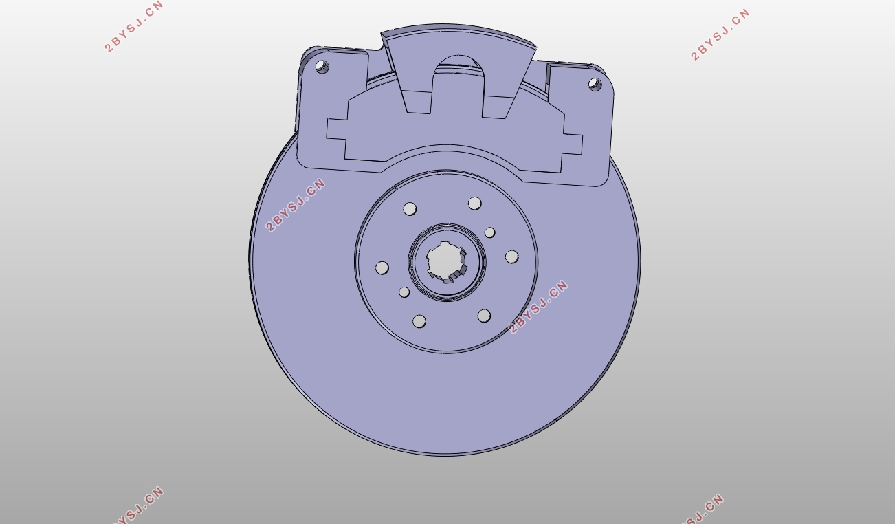
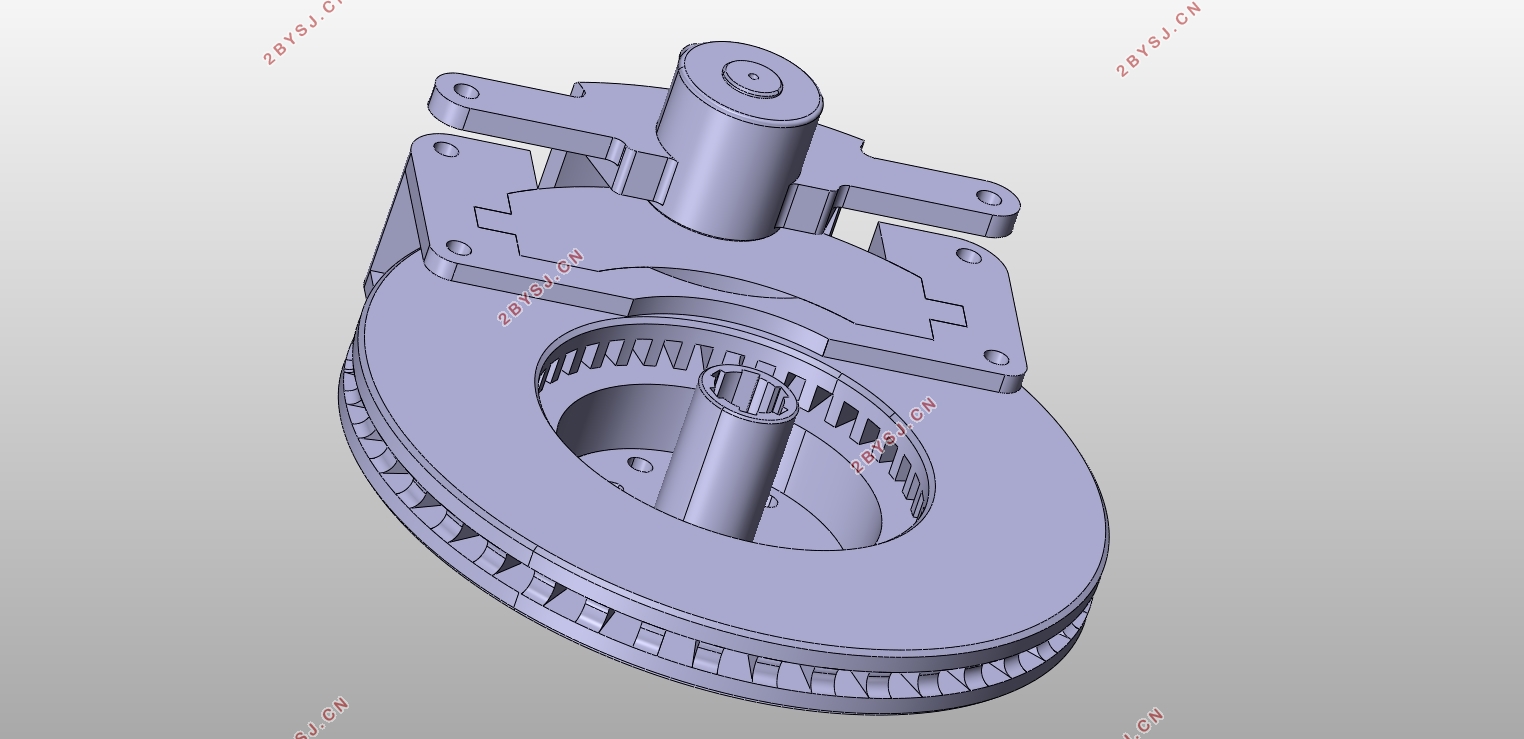
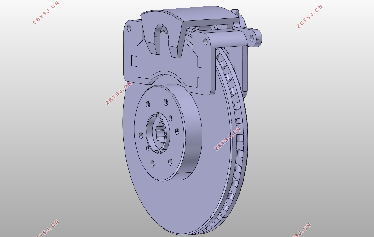
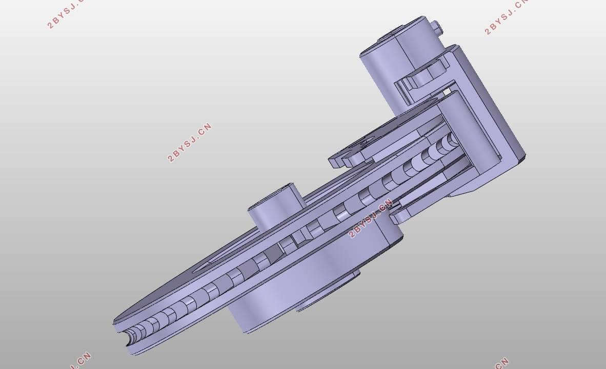
附录A 部分三维模型 30
附录B 用Matlab计算制动距离 33
致谢 34
