大众高尔夫变速器设计(含CAD零件装配图,CATIA三维图)
无需注册登录,支付后按照提示操作即可获取该资料.
大众高尔夫变速器设计(含CAD零件装配图,CATIA三维图)(任务书,开题报告,文献摘要,论文说明书10200字,CAD图7张,CATIA三维图)
摘 要
本次设计的内容是大众高尔夫的变速器,变速器是汽车内重要的零部件之一,变速器的主要功能是改变发动机所发出的转速与扭矩,使汽车可以的驱动力与转速可以在较大范围内变化。变速器的发展越来越快,本文对手动变速器与自动变速器的优劣进行了对比并进行了选型,阐述了变速器发展的必要性与必然性。并对变速器的发展现状以及未来发展有一些看法。
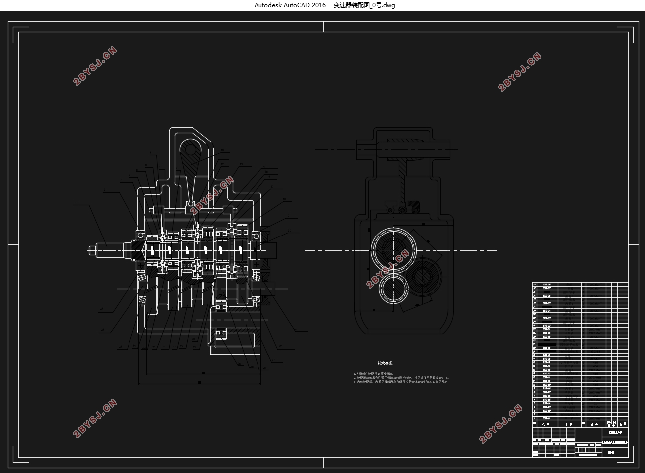
本篇文章主要内容是是针对大众高尔夫这款车的五档手动变速器设计,本次设计主要有变速器的总体方案设计,主要参数选择,各档传动比以及齿轮数的确定,齿轮尺寸的设计以及校核,轴的设计以及校核,还有同步器的设计与计算,并对变速器内轴进行可靠性分析与设计;同步器的设计与计算;最后使用AutoCad进行设计。
关键词:变速器;齿轮;同步器;轴
Abstract
The content of this design is the transmission. The transmission is one of the important parts in the car. The main function of the transmission is to change the speed and torque emitted by the engine, so that the driving force and the rotational speed of the car can be changed within a relatively large range. The development of transmissions is getting faster and faster. This article compares the merits and demerits of manual transmissions and automatic transmissions and selects models. It explains the necessity and inevitability of transmission development. And there are some opinions on the status quo and future development of the transmission.
The main content of this article is aimed at the VW Golf's five-speed manual transmission design. This design mainly includes the overall design of the transmission, the main parameter selection, the determination of the gear ratio and the number of gears in each gear, and the design of the gear size. Checking, design and verification of the shaft, design and calculation of the synchronizer, reliability analysis and design of the inner shaft of the transmission, design and calculation of the synchronizer, and final design using AutoCad.
Key Words: Transmission; Gear; Synchronizer; Shaft
.4.4轴承
本设计中齿轮与输出轴用滚针轴承,第一轴与输出轴跟箱体壳连接采用深沟球轴承,中间轴与箱体壳连接采用的是圆锥滚子轴承。
2.5传动方案
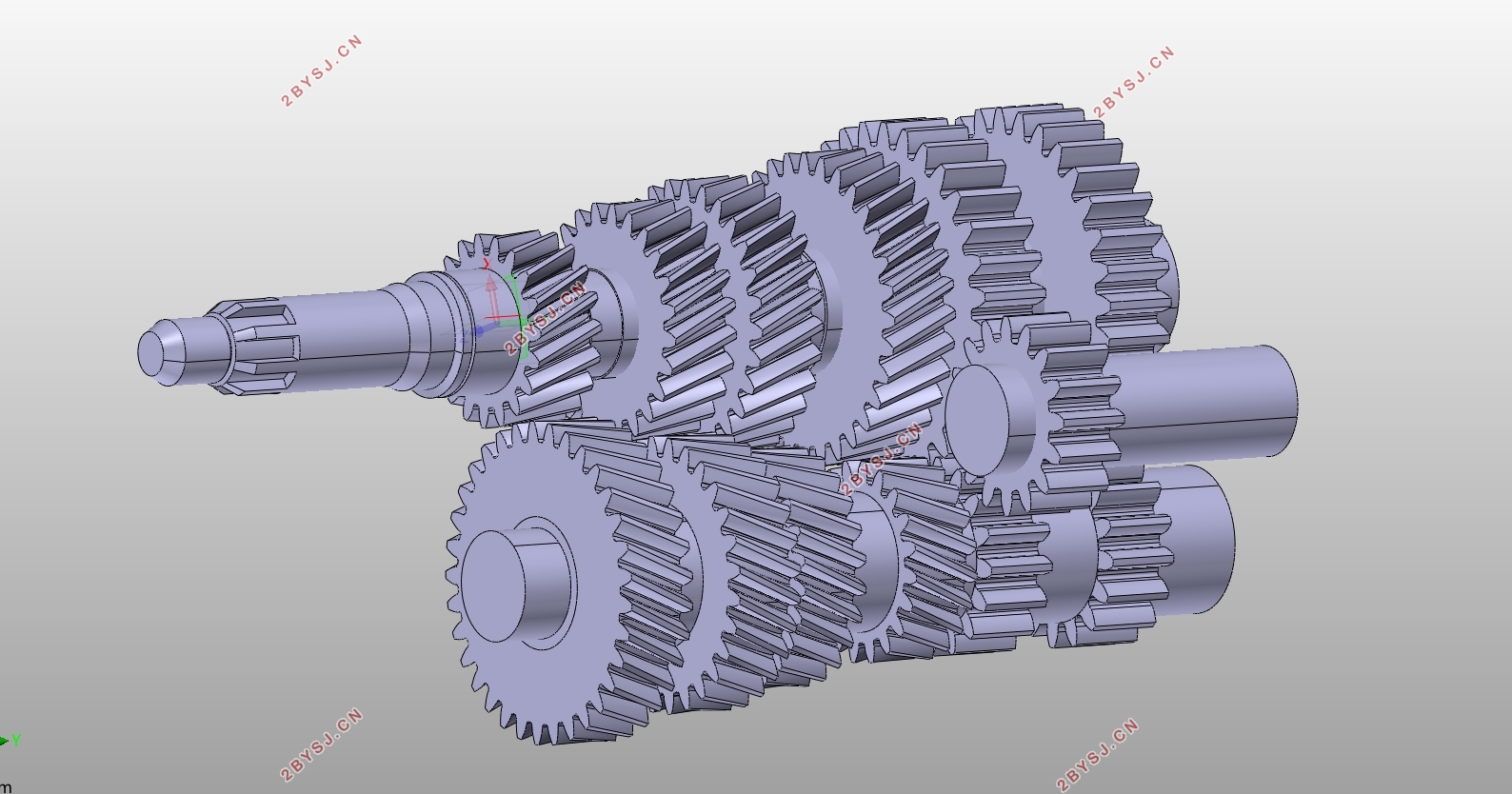
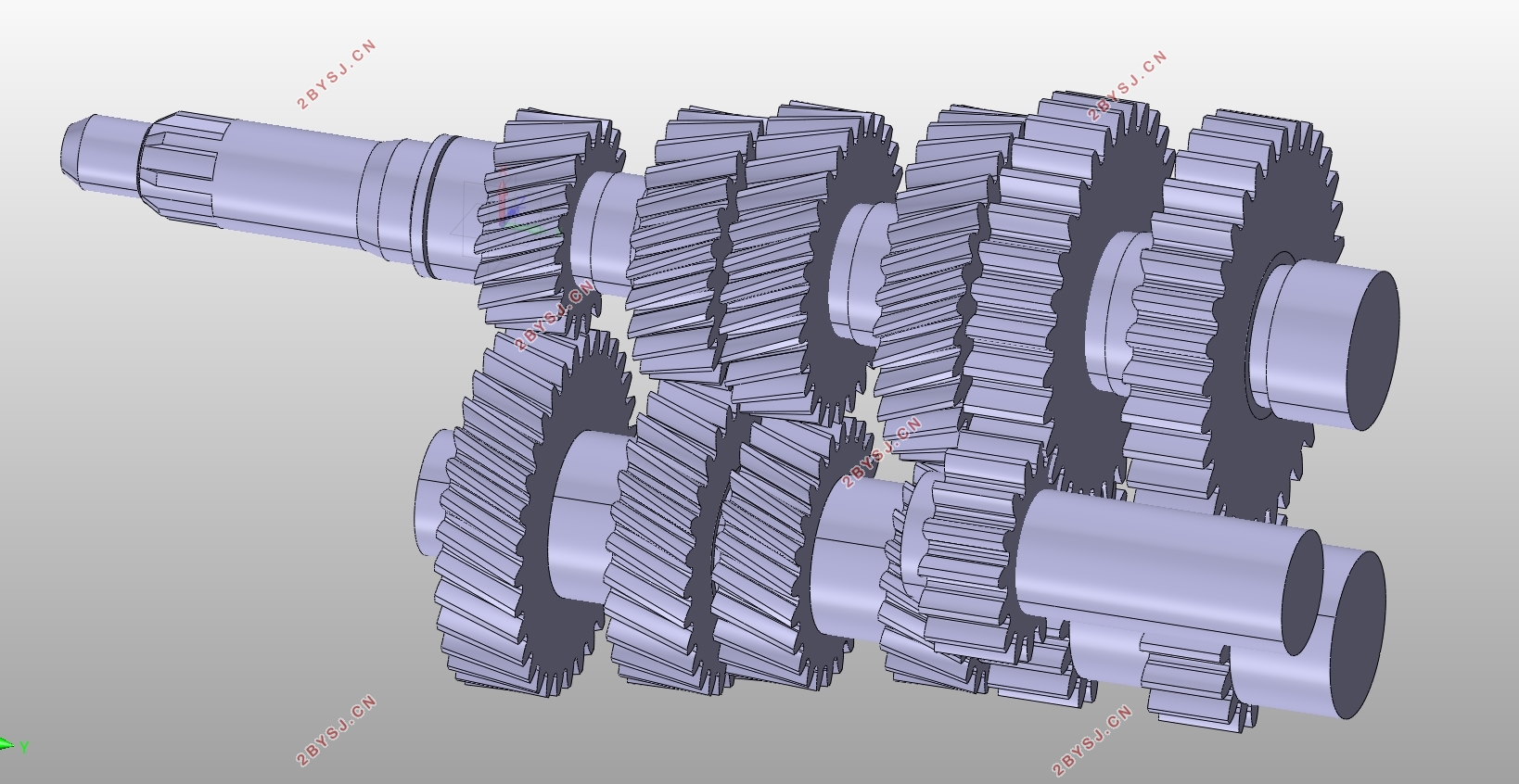
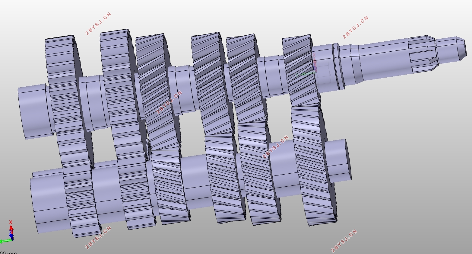
如图所示,传动路线为:
一挡:第一轴-1-2-13-12-输出轴;
二挡:第一轴-1-2-8-7-输出轴;
三挡:第一轴-1-2-6-5-输出轴;
四挡:第一轴-1-2-4-3-输出轴;
五挡:第一轴-1-输出轴。


目 录
第1章 绪论 1
1.1变速器设计的目的及意义 1
1.2变速器的发展现状 1
第2章 变速器的总体方案设计 3
2.1毕业设计任务及要求 3
2.2变速器的功用及设计要求 3
2.3变速器传动机构的型式选择与结构分析 3
2.4变速器主要零件参数计算 4
2.4.1齿轮 4
2.4.2轴 4
2.4.3同步器 4
2.4.4轴承 5
2.5传动方案 5
第3章 变速器主要参数选择与齿轮设计 6
3.1变速器主要参数选择 6
3.1.1档位数 6
3.1.2传动比范围 6
3.1.3中心距 7
3.1.4齿轮模数 8
3.1.5齿轮压力角 8
3.1.6螺旋角 8
3.1.7齿宽b 8
3.1.8变位系数的选择 9
3.2各挡传动比及齿轮数的确定 9
3.2.1一档齿轮数的确定 9
3.2.2确定常啮合齿轮副的齿数 9
3.2.3其他档位齿数的确定 10
3.2.4倒挡齿轮齿数确定 10
第4章 变速器齿轮强度计算与材料的选择 12
4.1齿轮的损坏形式 12
4.2齿轮强度计算 12
4.2.1轮齿弯曲强度计算 12
4.2.2齿轮的接触应力计算 14
4.3齿轮的尺寸 17
4.3.1直齿圆柱齿轮 17
4.3.2斜齿圆柱齿轮 18
第5章 变速器轴的设计与校核 19
5.1轴尺寸初选 19
5.2轴的结构形状 19
5.3轴的校核 19
5.3.1轴的刚度校核 19
5.3.2轴的强度校核 21
5.4轴的可靠性计算 23
第6章 同步器的设计 25
6.1同步器的结构 25
6.2同步器主要参数的确定 25
6.2.1锥面半锥角和摩擦系数 25
6.2.2同步环锥面上的螺纹槽 26
6.2.3摩擦锥面的平均半径R 26
6.2.4锥面工作长度b 26
6.2.5同步环径向厚度 27
6.2.6锁止角 27
6.2.7同步时间t 27
第7章 总结 28
参考文献 29
附 录A 30
附 录B 32
致 谢 33
