液压缸式弧形闸门启闭机控制系统设计(含CAD图)
无需注册登录,支付后按照提示操作即可获取该资料.
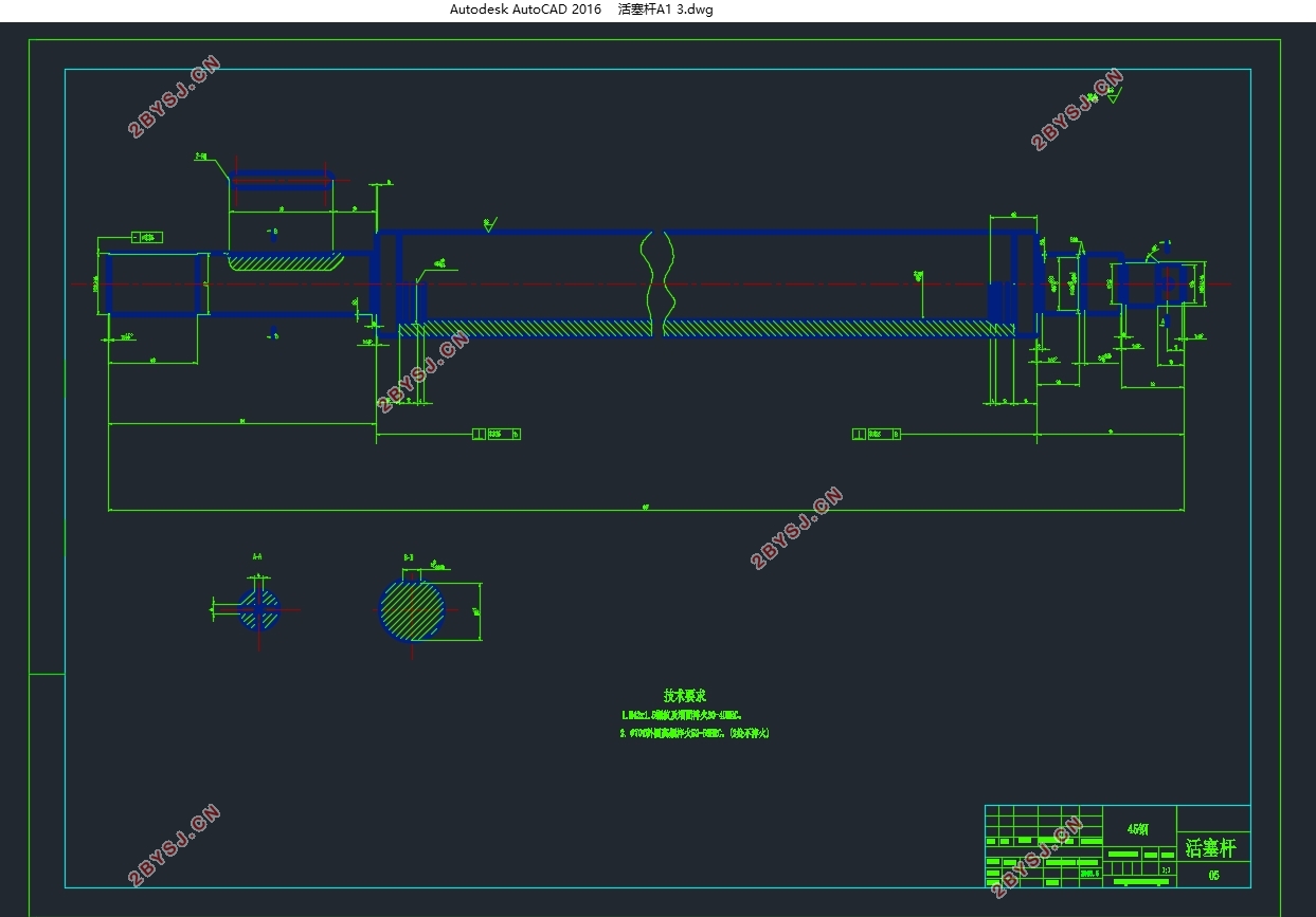
液压缸式弧形闸门启闭机控制系统设计(含CAD图)(论文说明书12000字,CAD图3张)
摘要
水力工程中重要的一个构成部分是闸门控制系统,随着通信技术、自动控制还有计算机技术的快速发展,这几年以来,用人力操作的闸门,它的简单的控制方法已经渐渐的不能实现水利的信息化要求。
本设计结合近几年水力工程的发展,通过液压元件具体的选型,设计了启闭机液压系统,理解之后画出了液压原理图。
设计中先是查阅资料对闸门结构工作原理进行一定程度以及发展程度进行一定的了解,接着,根据任务书中所给的流量与油压算出此次设计所需要的电机,画出油泵电机操作系统的原理运行图,再选择合适的低压电器以及传感器。了解液压系统的工作原理然后选择合适的液压元器件。
本设计运用可了S7-200PLC可编程控制器在闸门液压启闭机控制系统,取代了传统的继电器-接触器控制系统,了解PLC的应用问题选出合适的PLC模块,画出I/O接口图,并,对电机的正反转进行编程设计。
关键词:弧形闸门 启闭机 液压系统 PLC
Design of the Control System for the Hydraulic Cylinder Gate Hoist
Abstract
Gate control system is an important component part of reservoir engineering. with the continuous development of automatic control, communication and computer technology , by the gate of artificial operation, the control means and methods has been increasingly don’t adopt to the requirement of the water resources normalization.
The design of hydraulic components by specific selection, design a hoist hydraulic system after understanding the hydraulic schematic diagram.
Firstly, the design of access to information on the work principle of the gate structure to a certain extent and the degree of development of a certain degree of understanding, Then, according to the flow and the pressure of the task book to calculate the design of the motor, Drawing oil pump motor operating system operating system principle diagram, and then select the appropriate low-voltage electrical appliances and sensors. Understand the working principle of hydraulic system and select the appropriate hydraulic components.
This design introduces the PLC-based S7-200PLC gate hydraulic the hoist control system ,replacing the traditional relay and contactor control system。Understanding the application of PLC to select the appropriate PLC module, and drawing the I/O interface, and programming design for positive and negative of motor.
Key words: Gate; Hoist; Hydraulic system; PLC


目录
摘要 I
Abstract II
第1章 引言 1
1.1背景 1
1.2.设计的主要内容 2
第2章 闸门及工作原理 4
2.1 水工闸门 4
2.2闸门选择 4
2.3弧形闸门工作原理 4
2.4小结 5
第3章 液压系统设计 6
3.1液压系统 6
3.2工作原理 6
3.3液压元器件选型 7
3.3.1油箱 7
3.3.2吸油滤油器 8
3.3.3电磁溢流阀 9
3.3.4弹簧压力表 10
3.3.5油缸 10
3.3.6球阀 10
3.3.7压力继电器 11
3.3.8液控单向阀 12
图3-9 液控单向阀 12
3.3.9换向阀 12
3.4小结 14
第4章 油泵电机控制设计 15
4.1油泵电机的选择 15
4.1.1系统设计参数 15
4.2油泵电机控制原理图 16
4.3控制电路中低压电器的选型 17
4.3.1热继电器 17
4.3.2熔断器 17
4.3.3交流接触器KM选择 19
4.3.4三相刀开关QS 20
4.3.5.空气开关QF 20
4.4传感器选择 21
4.4.1油箱温度传感器 21
4.4.2.压力传感器 22
4.4..3电压传感器 24
4.4.4液位传感器 25
4.5小结 27
第5章 PLC控制系统设计 28
5.1 PLC概述 28
5.2 SIEMENS PLC 模块选择及简介 29
5.2.1PLC模块选择 29
5.2.2 PLC模块的简介 30
5.3PLCI/0分配及接口图 30
图5-1 I/O接口图 30
5.3.1PLCI/O分配 31
5.4编程 32
5.5流程图 34
5.6控制面板图 35
5.7小结 36
参考文献 37
致谢 39
