
液压制动系统电动助力机构设计(含CAD零件图装配图,CATIA三维图)
无需注册登录,支付后按照提示操作即可获取该资料.
液压制动系统电动助力机构设计(含CAD零件图装配图,CATIA三维图)(任务书,开题报告,文献摘要,外文翻译,论文说明书12000字,CAD图纸7张,CATIA三维图)
摘要
汽车自1886年发明到现在已发展了131年,现在的汽车发展主题已经变成了节能、环保和安全。俗话说人命关天,汽车的安全性能恰恰决定着驾驶员、乘客以及行人的生命安全,可见汽车安全性之重要。随着汽车发动机技术的飞速发展,汽车的行驶速度越来越快,如何让急速行驶的汽车停下来就是汽车安全性要重点考虑的问题。本文题目是液压制动系统电动助力机构设计,通过对传统汽车制动系统的介绍,结合现阶段制动系统电动助力机构的发展现状,分析设计一套液压制动系统电动助力机构,旨在使汽车制动响应更快、制动距离更短。更外,这套机构还可以实现汽车的更节能、更智能。
关键词:安全、制动系统、电动助力、齿轮
Abstract
Since the invention of the car in 1886 has now developed for 131 years, the current car development theme has become energy saving, environmental protection and safety. As the saying goes, life safety, car safety performance determines the driver, passengers and pedestrians of life safety, we can see the importance of car safety. With the rapid development of automotive engine technology, car driving faster and faster, how to make the rapid driving of the car to stop is to focus on car safety issues to be considered. This paper focuses on the design of the electric brake mechanism of the hydraulic braking system. Through the introduction of the traditional automobile braking system and the present situation of the electric power assisting mechanism of the braking system at present, the hydraulic control system is designed and manufactured. The brake response is faster and the braking distance is shorter. Moreover, this set of institutions can also achieve the car more energy efficient, more intelligent.
Key Words:safety, brake system, electric power, gear


目录
第1章绪论 1
1.1传统制动系统简介 1
1.1.1 制动系统的基本机构和发展现状 1
1.1.2 制动系统的基本功能和设计要求 2
1.1.3 制动系统的性能分析 2
1.2 电动助力液压制动系统概况 7
1.2.1 电动助力液压制动系统的研究目的和意义 7
1.2.2 电动助力液压制动系统的发展现状 8
1.3 研究内容 8
第2章电动助力机构方案的确定 9
2.1 方案的选择及其控制原理 9
2.2 该方案的优点及要求 10
第3章传统制动系统参数的设计 12
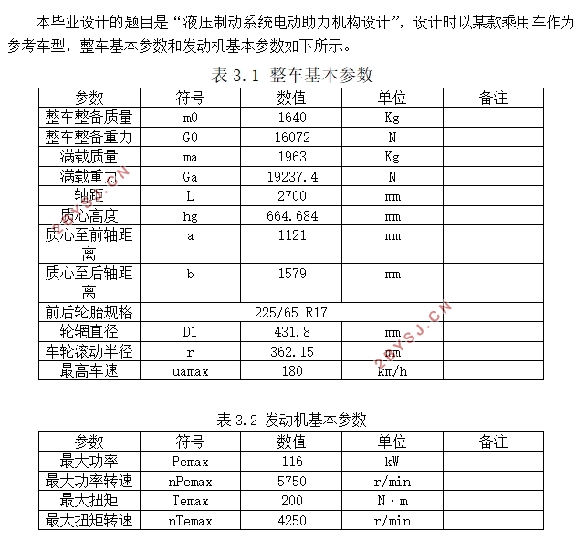
3.1 设计基本参数 12
3.2 同步附着系数 的选取 12
3.3 制动时地面对前后轮的法向反作用力 13
3.4 制动器制动力矩的计算 14
3.5 制动系统主要零部件的设计 15
3.5.1 制动盘 15
3.5.2 摩擦衬块 15
3.5.3 单侧制动块对制动盘的压紧力 16
3.5.4 制动轮缸直径 16
3.5.5 制动主缸直径 17
3.6 制动踏板力和制动踏板工作行程 17
3.7 制动距离校核 18
3.8 本章主要参数汇总 18
第4章电动助力机构参数的设计 20
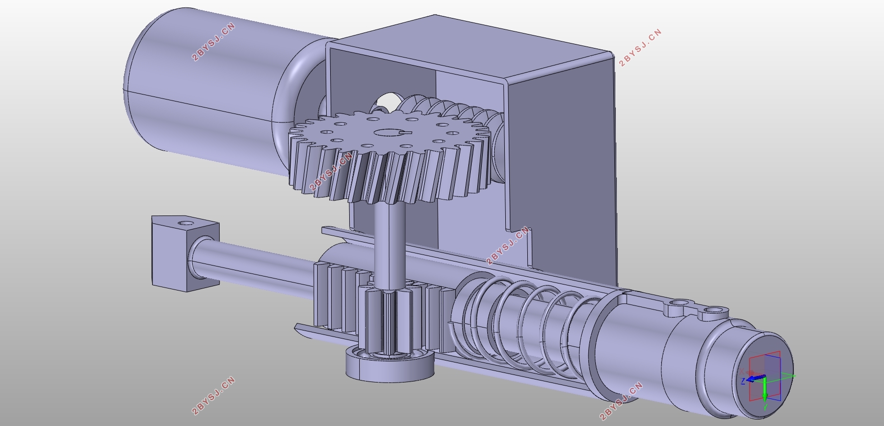
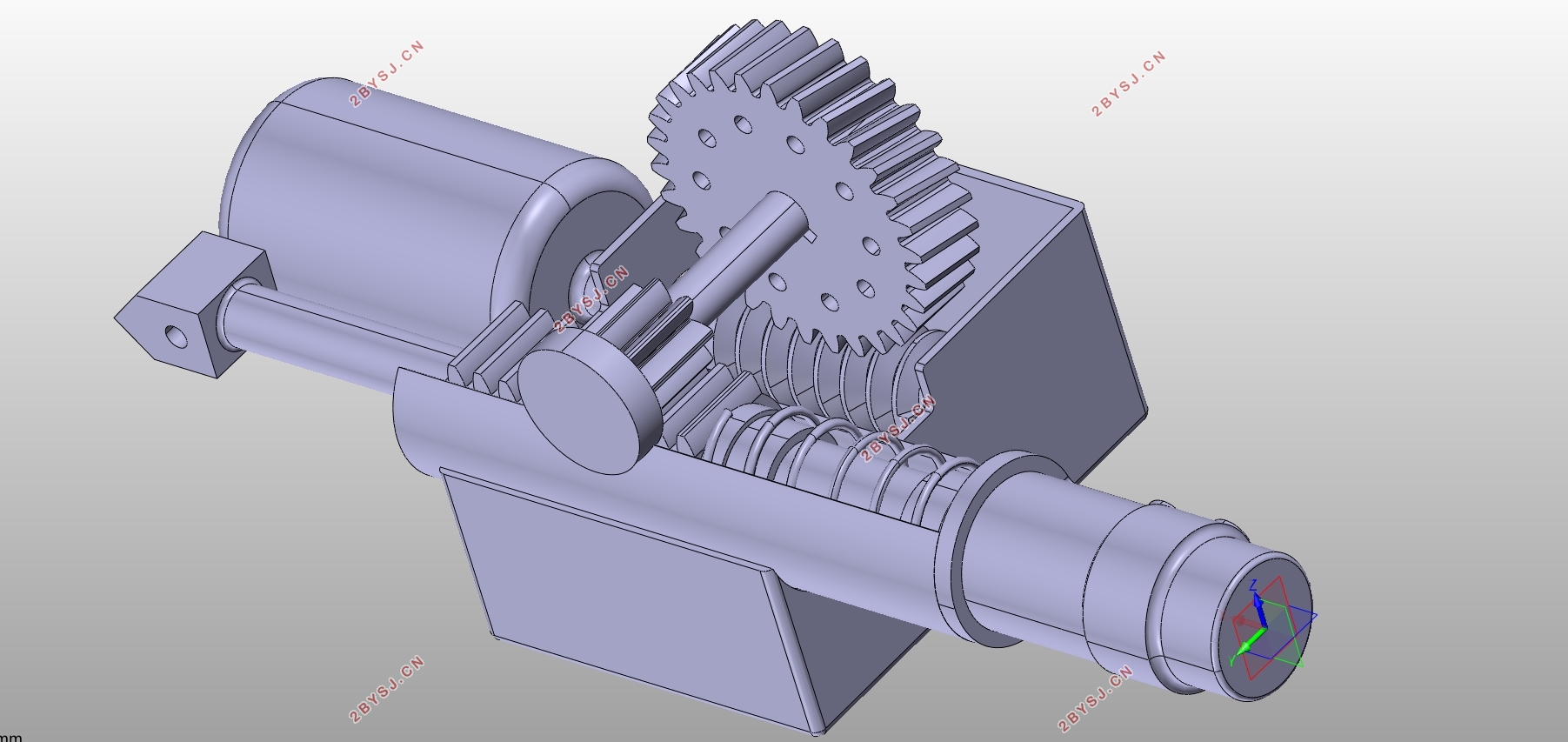
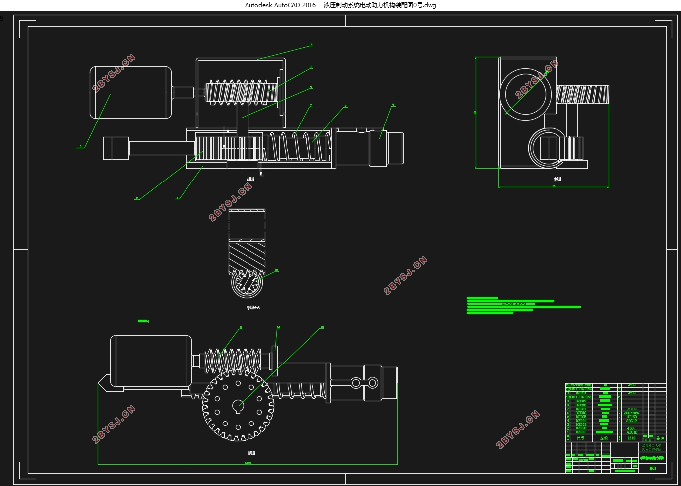
4.1 二级齿轮减速机构的设计和校核 20
4.1.1 蜗轮蜗杆传动机构的设计 20
4.1.2 齿轮齿条传动机构的设计 21
4.1.3 蜗杆传动的校核 23
4.2 助力电机的选型 24
4.2.1额定功率的选择 24
4.2.2 额定转速的选择 25
4.2.3 电机选择的验算 25
4.2.4 电机型号的确定 25
4.3 助力机构三维模型的建立 26
第5章全文总结 27
参考文献 28
致谢 29