
燃料电池客车制动系统设计(含CAD零件图装配图,CATIA三维图)
无需注册登录,支付后按照提示操作即可获取该资料.
燃料电池客车制动系统设计(含CAD零件图装配图,CATIA三维图)(任务书,开题报告,文献摘要,论文说明书14000字,CAD图纸5张,CATIA三维图)
摘要
随着现代汽车技术的发展日益壮大,伴随着的是人们对于汽车安全性能的要求越来越大,燃料电池客车的出现,为客车市场的持续发展推开了一扇新的大门。所以进一步提高客车整车的安全性能和保证其可靠性也是客车技术发展十分重要的一步,汽车的制动性能就是其中一个十分关键的参数,所以对其进行的设计研究具有重要的现实意义。
本次设计主要是在对燃料电池客车制动系统结构进行设计分析的基础上,根据燃料电池客车整体参数和性能要求,设计出符合标准的合理可靠的制动系统。制动系统的设计是在主要参数的基础上,我们选择适当的结构方案,设计决定前后制动器的主要结构尺寸等。最后对制动效能有一个简单分析和评价,再对制动系统的部分主要元件进行应力应变计算及仿真分析。
关键词:燃料电池客车;制动;气压盘式制动器;热力学仿真;Workbench
Abstract
With the development of modern automobile technology, the requirement of automobile performance catch more and more attention. The fuel cell bus has opened a new door for the development of the passenger car market. And further improving the safety performance of the bus and ensuring its reliability are also very important in the development of safety technology. The brake system of the automobile is one of the most important parameters. So it is very important to design a reliable brake system.
This design is mainly on the fuel cell bus brake system based on the analysis of the design. According to the fuel cell bus overall parameters and performance requirements, to design a reliable braking system. The design of the braking system is based on the main parameters, and a reasonable structure is chosen to design the main structure size of the brake. Finally, some parts of the braking system are simulated and analyzed, and the braking efficiency is analyzed and evaluated.
Key words: Fuel cell bus; Brake; Air disc brake; Thermodynamic simulation; Workbench
制动系主要参数的确定
3.1燃料电池客车主要参数
某燃料电池客车基本参数:
(1) 轴距:L=6000mm
(2) 最高车速:v=69km/h
(3) 汽车空载质量:12000kg;汽车满载质量:17000kg
(4) 空载时质心高度:0.9m;满载时质心高度:1.2m
(5) 轴荷(kg):6410/10590
(6) 轮辋直径:查阅资料选用轮胎型号为295/80R22.5,计算得轮辋直径为0.5715m
(7) 质心到前后轴距离a/b(mm):3932/2068
目录
第1章 绪论 1
1.1汽车制动系设计的意义 1
1.2汽车制动系设计的目的 1
1.3汽车制动系设计的要求 1
1.4国内外研究现状 2
1.5本章小结 2
第2章 制动系结构形式的确定 3
2.1制动器类型确定 3
2.2制动器结构型式选择 3
2.4制动回路形式选择 4
2.5本章小结 5
第3章 制动系主要参数的确定 6
3.1燃料电池客车主要参数 6
3.2车辆制动时受力分析 6
3.3同步附着系数的确定 9
3.4制动器效能因数 10
3.5本章小结 11
第4章 制动系结构设计 12
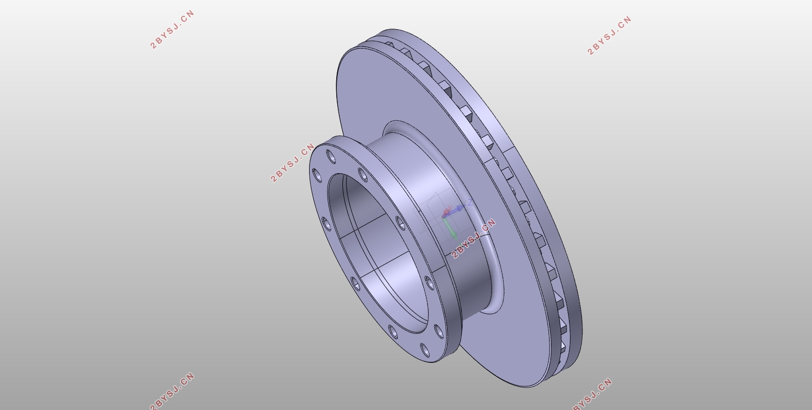
4.1制动器结构设计 12
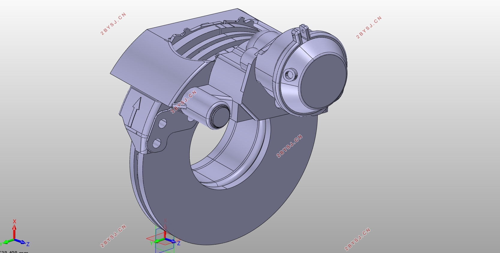
4.1.1制动盘 12
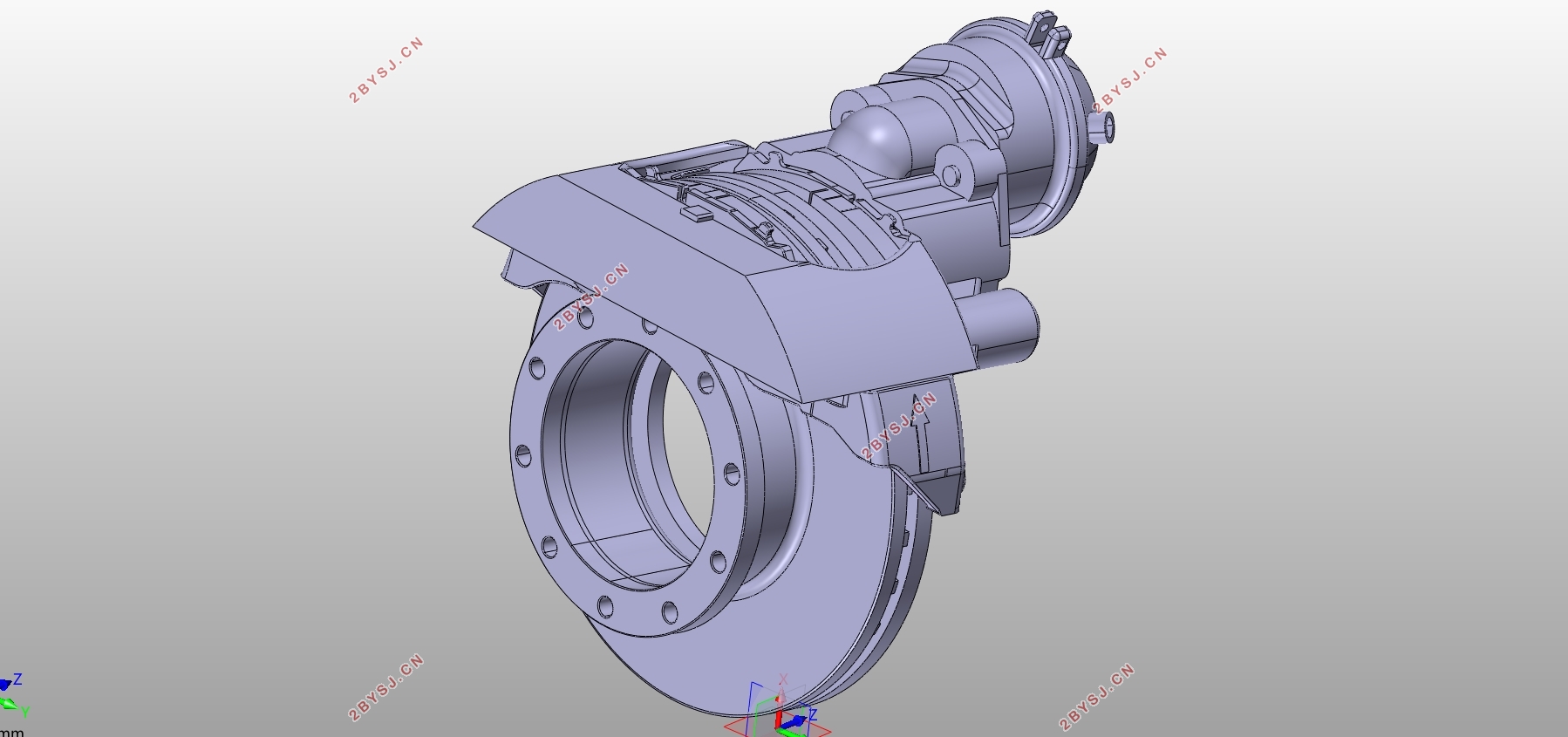
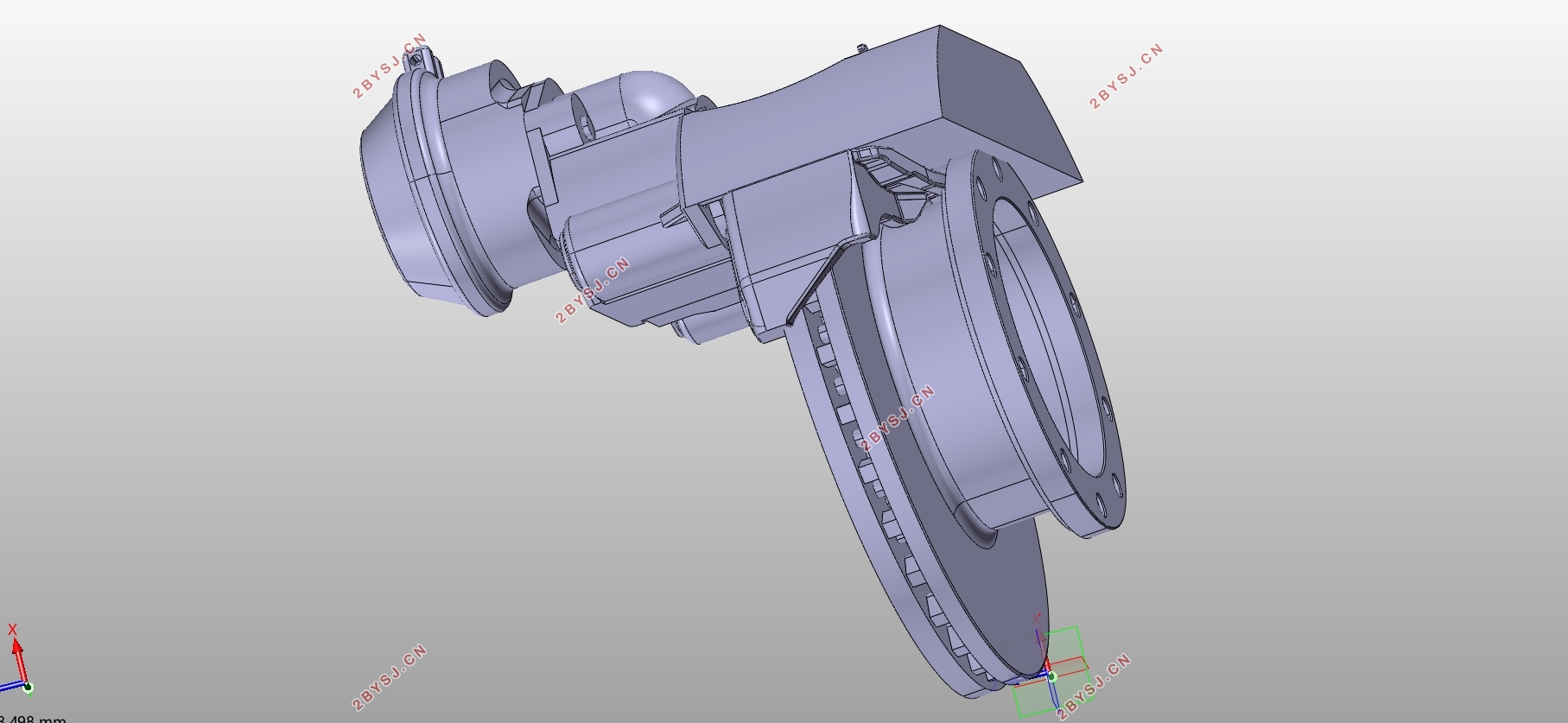
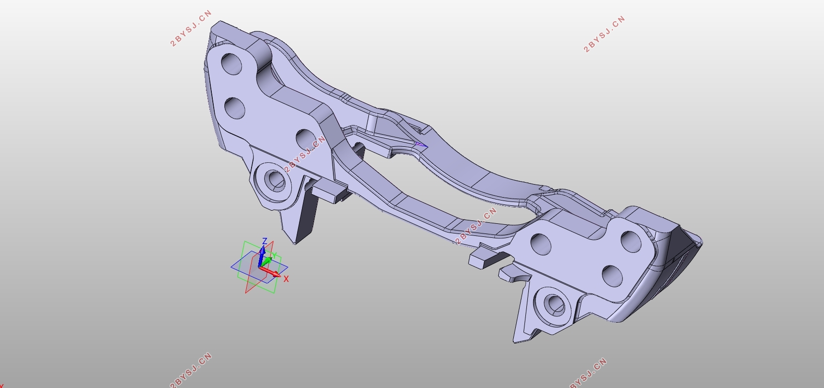
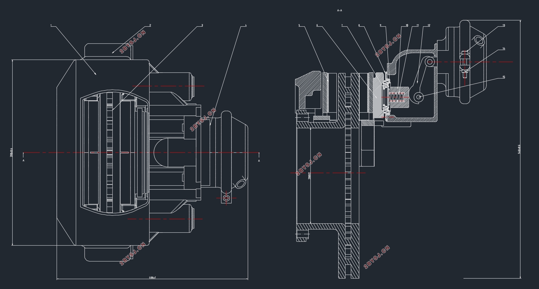
4.1.2制动钳 13
4.1.3制动块 13
4.2气压制动系统驱动机构设计 15
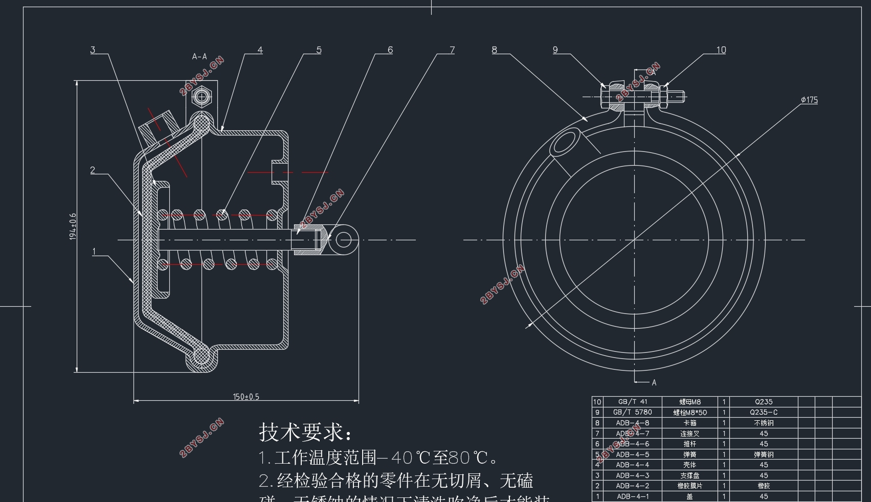
4.2.1制动气室 15
4.2.2储气筒 15
4.2.3制动气泵 17
4.2.4控制阀 18
4.2.5保护阀 18
4.3制动性能评价 19
4.4本章小结 20
第5章 制动器热力学仿真 21
5.1制动器热力学基本理论 21
5.1.1热传递方式 21
5.1.2接触分析理论 21
5.1.3制动摩擦生热理论 22
5.2热分析模型的建立 22
5.2.1简化模型 22
5.2.2接触、载荷和边界条件 23
5.2.3划分网格 24
5.3稳态仿真分析 24
5.4瞬态仿真分析 26
5.5本章小结 29
第6章 总结与展望 30
6.1设计总结 30
6.2展望 30
参考文献 31
致谢 31