90度弯头坡口端面组合铣床设计(专用夹具)(含CAD零件图夹具装配图)
无需注册登录,支付后按照提示操作即可获取该资料.
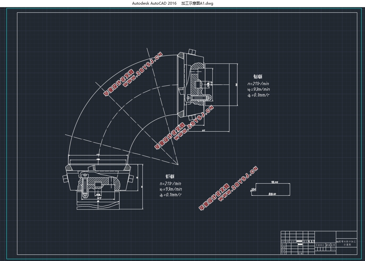
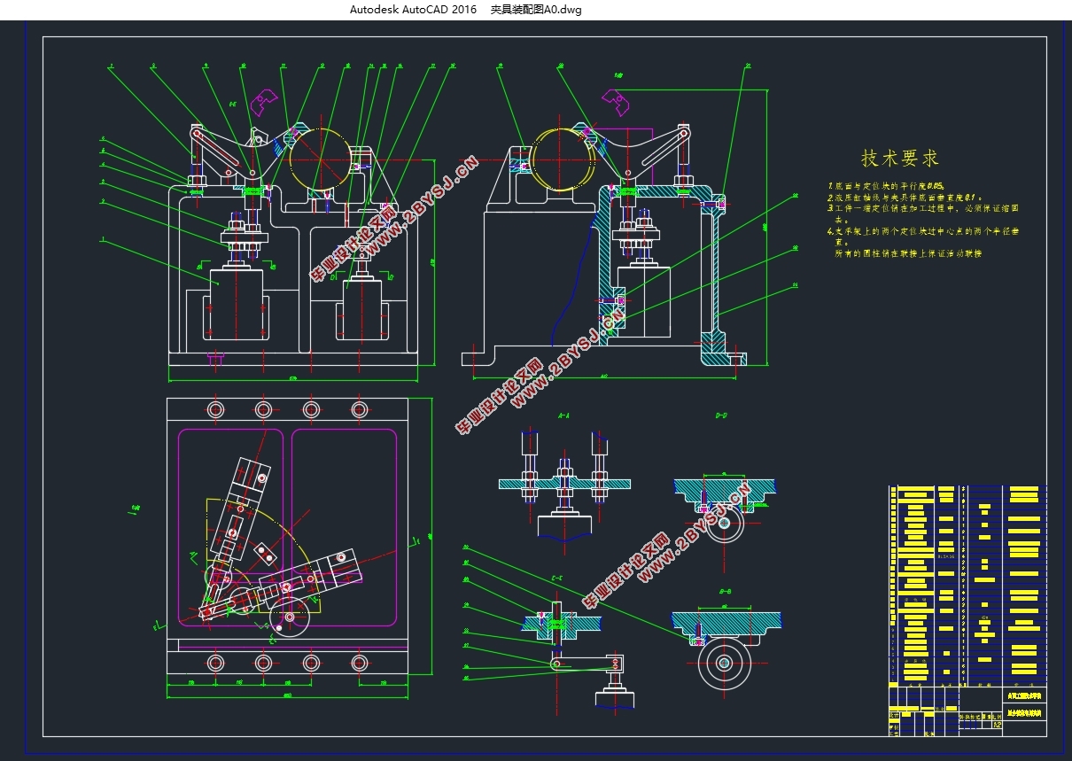
90度弯头坡口端面组合铣床设计(专用夹具)(含CAD零件图夹具装配图)(论文说明书18000字,外文翻译,CAD图8张)
摘 要
针对目前加工钢管坡口方法的质量差、成本高、效率低、劳动强度大、质量难以控制等问题,设计了一种90度弯头坡口端面加工组合机床以及专用夹具。利用该设备可实现90度弯头坡口端面的可靠定位及夹紧,完成循环加工过程。较大地降低劳动强度,提高生产效率,为90度弯头的坡口加工提供了可靠的技术保证,具有良好的经济效益和应用价值。
机械制造过程及检测,检验中,都要使用大量的夹具。夹具是能够使产品按一定的技术要求准确定位和牢固夹紧的工艺装置,它的主要用于保证产品的加工质量、减轻劳动强度、辅助产品检测、展示、运输等。因此,如何设计好机床夹具则成了机械制造的一项重要任务。
本文专门设计了一种铣床夹具,通过对夹具的定位方案,夹紧方案、对刀方案,夹具体与定位键的设计及加工精度等方面的分析和实践应用,证明能满足工艺和生产要求。
关键词:90度弯头坡口;组合机床;专用夹具……
Abstract
Aiming at the problems of poor quality, high cost, low efficiency, high labor intensity and difficult quality control of the current method for processing steel pipe groove, a 90 degree elbow groove end face processing combined machine tool and a special fixture are designed. The equipment can be used to realize reliable positioning and clamping of the bevel end face of a 90-degree elbow and complete the cyclic processing process. It greatly reduces labor intensity, improves production efficiency, provides reliable technical guarantee for bevel processing of 90-degree elbow, and has good economic benefits and application value.
A large number of jigs are used in the mechanical manufacturing process, testing and inspection. Fixture is a technological device that can accurately position and firmly clamp products according to certain technical requirements. It is mainly used to ensure the processing quality of products, reduce labor intensity, and assist product inspection, display, transportation, etc. Therefore, how to design the machine tool fixture has become an important task in mechanical manufacturing.
This paper specially designs a kind of milling machine fixture. Through the analysis and practical application of the fixture's positioning scheme, clamping scheme, tool setting scheme, fixture body and positioning key design and machining accuracy, it is proved that it can meet the technological and production requirements.
Key words:90 degree elbow groove; Modular machine tools; Special fixture……
设计方案比较:
方案一:用普通铣床单独加工坡口和端面。采用此方案适用范围广,加工设备简单,但难以保证其加工精度,加工时间长,不适用大批量加工。
方案二:用车床车削坡口和端面。采用此方案通用性好,适用范围广,但加工装夹复杂,需要对车床进行改造,生产成本高,且加工复杂。
方案三:用组合铣床铣削90度弯头坡口端面配以专用夹具夹紧工件。采用此方案加工具有高精度、高效率、高柔性、降低劳动强度和拓宽工艺范围等特点。可进行批量生产且符合精度要求。
综上所述,第三种方案不仅可以满足加工精度等基本要求,而且还可以实现批量生产,提高加工效率。所以最终选取第三种方案。


目录
二〇一九年六月 1
1 绪论 1
1.1 课题来源与意义 1
1.2 组合机床的特点 2
1.3 组合机床的方案选择 3
1.3.1 制定工艺方案 3
1.3.2 机床结构方案的分析和确定 3
2 组合机床方案的确定 1
2.1 被加工零件的加工精度和加工工序分析 1
2.2 被加工零件材料特点分析 1
2.3 零件的定位与夹紧分析 1
2.4 零件的加工工艺分析和比较 3
3 组合机床的分类和确定基本配置形式 4
4 2.6 经济分析 4
5 3 确定切削用量及刀具选择 6
6 3.1 确定切削用量参数 6
7 3.1.1 确定加工余量 6
8 3.1.2 确定切削用量 6
9 3.2 确定切削力及切削功率 8
10 3.2.1 切削力及切削功率参数公式 8
11 3.2.2 计算切削力及切削功率 9
12 3.3 刀具材料选择 9
13 3.4 硬质合金端铣刀的设计 10
14 3.4.1 概述 10
18 3.4.2 硬质合金端铣刀几何角度的合理选择 12
20 3.4.3 不重磨端铣刀刀片的定位与夹紧结构 15
21 3.4.4 端铣刀主要结构参数 16
22 3.4.5 刀槽尺寸及刀齿几何角度计算 16
24 4 组合铣床总体设计 20
25 4.1 被加工零件工序图 20
26 4.2 加工示意图 20
27 4.2.1 加工示意图的作用及内容 20
28 4.2.2 刀具的选择 21
29 4.2.3 确定主轴类型、尺寸及外伸长度 22
30 4.2.4 确定动力部件的工作循环和工作行程 22
31 4.3 组合铣床联系尺寸图 23
32 4.3.1 机床联系尺寸图的作用和内容 23
33 4.3.2 绘制机床尺寸联系总图之前应确定的内容 23
34 4.4 生产率计算卡 25
35 5 专用夹具设计 28
36 5.1 夹具概述 28
37 5.1.1 夹具分类 28
38 5.1.2 机床夹具的现状 28
39 5.1.3现代机床夹具的发展方向 29
40 5.2 夹具设计任务 29
41 5.3 拟定夹具结构方案 29
42 5.3.1 确定工件定位方案及设计选择定位装置 29
43 5.3.2 确定工件夹紧方案及设计选择夹紧装置 30
44 5.3.3 夹具体设计 31
45 5.4分析定位误差 31
46 5.5 夹紧力的分析计算 31
49 5.6 夹具操作说明 34
50 5.7 绘制铣床夹具装配图 35
51 结 论 35
52 参考文献 37
53 外文资料 39
54 中文译文 49
致 谢 55
