
主架体单工位镗孔组合机床主轴箱设计(含CAD零件图装配图)
无需注册登录,支付后按照提示操作即可获取该资料.
主架体单工位镗孔组合机床主轴箱设计(含CAD零件图装配图)(任务书,开题报告,外文翻译,论文说明书10000字,CAD图7张,答辩PPT)
摘要
主轴箱是组合机床的重要专用部件。它是根据加工示意图所确定的工件加工孔的数量和位置、切削用量和主轴类型设计的传递各主轴运动的动力部件。其动力来自通用的动力箱,与动力箱一起安装于进给滑台,可完成钻、扩、铰、镗孔等加工工序。
主轴箱一般具有多根主轴同时对一列孔系进行加工。但也有单轴的,用于镗孔居多。主轴箱按结构特点分为通用(即标准)主轴箱和专用主轴箱两大类。前者结构典型,能利用通用的箱体和传动件;后者结构特殊,往往需要加强主轴系统刚性,而使主轴及某些传动件必须专门设计,故专用多轴箱通常指“刚性主轴箱”,即采用不需刀具导向装置的刚性主轴和用精密滑台导轨来保证加工孔的位置精度。通用多轴箱则采用标准主轴,借助导向套引导刀具来保证加工孔的位置精度。通用多轴箱又大型多轴箱和小型多轴箱,这两中多轴箱的设计方法基本相同。
本课题主要设计大型通用主轴箱。大型通用主轴箱由通用零件如箱体、主轴、传动轴、齿轮和附加机构等组成。
关键词: 组合机床 主轴箱 设计
The main axle box body single-position portfolio boring machine design of main frame
Abstract
Spindle box of Modular Machine Tool is an important private parts. It is based on the process diagram to determine the number and location of workpiece machining of holes, cutting pass the spindle and spindle type design power part of the campaign.Its power from the general of the box, and power box are installed in the feeding stage, to complete processing such as drilling, expanding, hinged, boring .
Spindle box generally has a plurality of spindle and the processing of the column holes. But there are also single shaft, used for boring. According to the structure characteristics of the spindle box is divided into general (standard) spindle box and a dedicated spindle box two categories. The structure of a typical, common box and transmission parts use; the latter structure is special, often need to strengthen the spindle system rigid, and make the spindle and certain transmission parts must be specially designed, so the special case usually refers to "rigid spindle box", namely the rigid spindle without tool guiding device and precision slide rail to ensure position precision machining hole. General multi-axle box adopts standard spindle, with the help of the guiding sleeve guide tool to ensure the position precision machining hole. General multi-axle-boxes and large ones and small box, basically the same design method of the two in box。
The main design of large universal spindle box. Large universal spindle box is composed of general parts such as consisting of a box body, shaft, drive shaft, gear and additional mechanism etc.
Keywords: spindle box of modular machine tool design

目录
摘要 I
Abstract II
第一章 绪论 1
1.1 引言 1
1.1.1 组合机床的国内现状 1
1.1.2 组合机床国外现状 2
1.2 课题介绍 3
1.2.1 设计内容 3
1.2.2 设计要求 3
1.3 组合机床的设计步骤 4
1.3.1 调查研究 4
1.3.2 拟定方案 4
第二章 组合机床总体设计 5
2.1 被加工零件工序图 5
2.1.1 被加工零件工序图的作用与内容 5
2.2 加工示意图 5
2.2.1 加工示意图的作用和内容: 5
2.2.2选择刀具、导向及有关计算 5
2.3 机床联系尺寸图 6
2.3.1 机床联系尺寸图作用和内容: 6
2.3.2 绘制机床尺寸联系总图之前应确定的内容: 7
第三章 组合机床主轴箱的概述 9
3.1 多轴箱的组成 9
3.1.1 通用箱体类零件 9
3.1.2 通用主轴 9
3.1.3 通用传动轴 9
3.1.4 通用齿轮和套 9
3.2 通用多轴箱的工作原理和用途 9
第四章 主轴箱设计 11
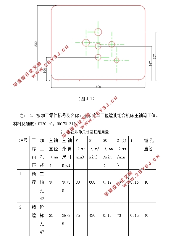
4.1 主轴箱设计的原始依据 11
4.2 主轴箱轴径的确定,可需功率 13
4.3 对多轴箱传动系统的一般要求 14
4.4 主轴箱轴承的选取,排列,间隙调整,轴上零件与轴承的润滑 14
4.4.1 主轴箱轴承的选取 14
4.4.2 轴承排列 15
4.4.3 轴承间隙的调整 15
4.4.4 轴上零件与轴承的润滑 15
4.4.5 主轴箱油面高度的确定 15
4.5 主轴箱的坐标计算 16
4.6 主轴齿轮的校核 22
第五章 绘制多轴箱总图及零件图 30
5.1 多轴箱总图设计 30
5.2 多轴箱零件设计 32
结语 34
参考文献 35
致谢 36