厚板料冲小孔(钩钉块)冲压模具设计及有限元分析(含CAD零件装配图,PROE三维
无需注册登录,支付后按照提示操作即可获取该资料.
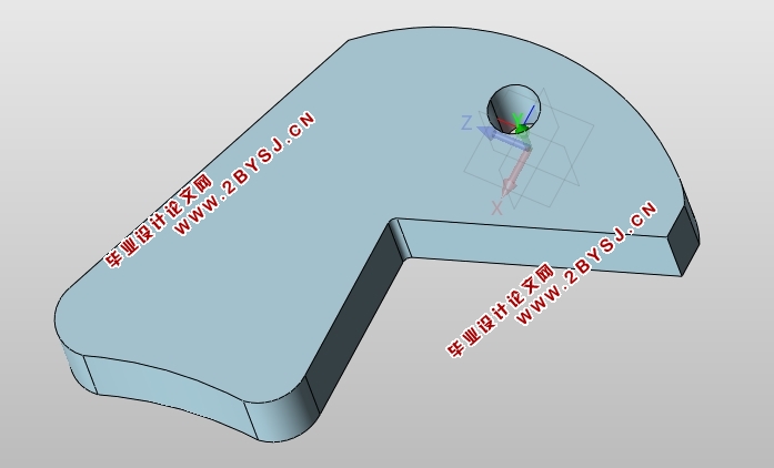
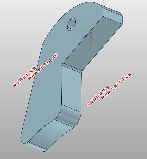
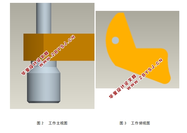
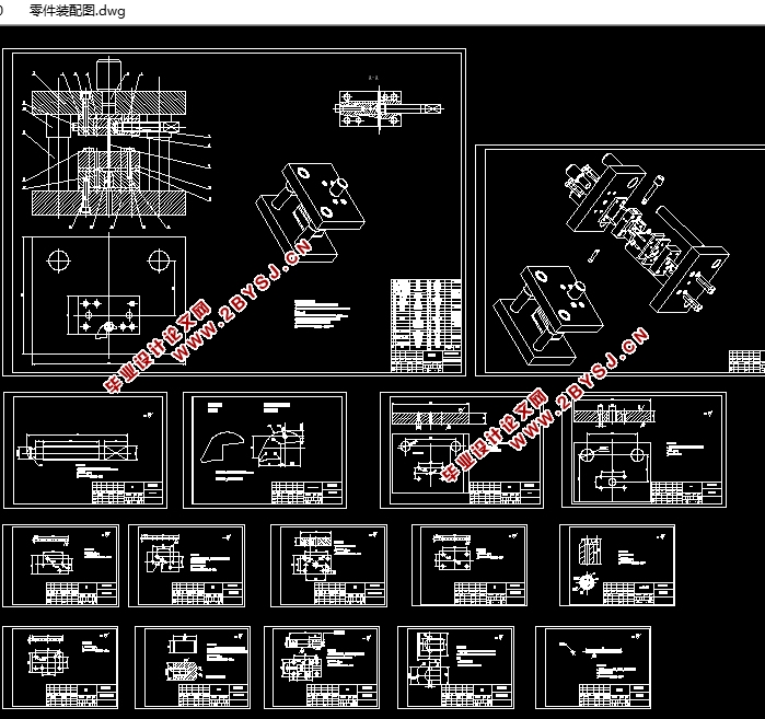
厚板料冲小孔(钩钉块冲压)模具设计及有限元分析(含CAD零件图装配图,PROE三维图)(任务书,开题报告,中期检查表,外文翻译,论文说明书17000字,CAD图纸16张,PROE三维图)
摘 要
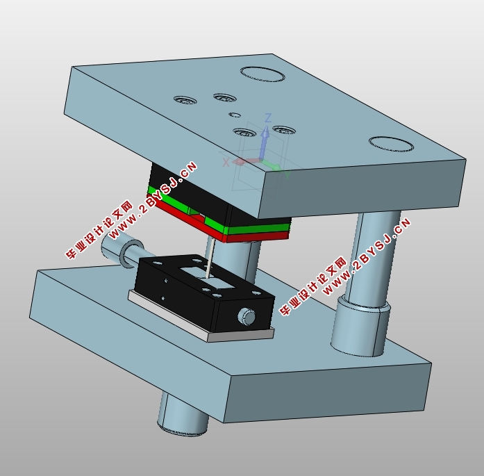
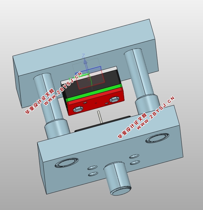
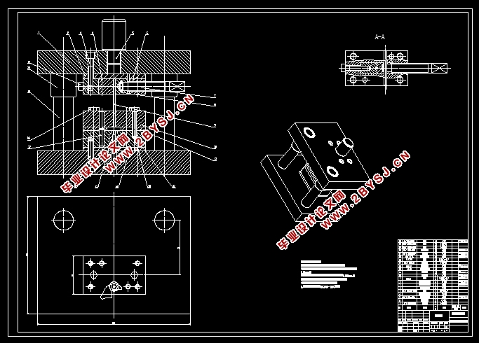
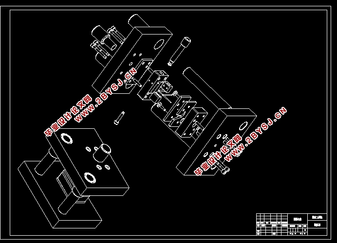
本文详细地阐述了厚板料冲小孔模具的设计及有限元模拟过程。首先简明叙述了现代国内外模具发展概况,通过有限元模拟分析模具可能出现的问题,然后重点设计了冲裁模具中相关部件,如凹凸模、模架设计以及压力机选择,并对冲压材料性能进行了分析。最后根据冲裁件的产品数量要求,以及结构要求,设计出来整套模具。整个设计过程都是用CAD、Pro/Engineering软件进行参数化设计,使整个模具设计过程简单明了。利用DEFORM软件进行有限元模拟分析,为模具设计和成型工艺的指定提供参照依据。
在设计过程中首先使用CAD软件设计成型零件以及非标零件,然后在Pro/Engineering软件中实现三维实体设计,最后导入DEFORM中,分析工件上选取点的应力、应变以及应变速率等相关因素,从而完成模具的整体设计以及有限元模拟,对直接指导生产有一定的意义。
关键词 :厚板料;冲小孔;参数化设计;有限元模拟
ABSTRACT
The design of a die used for punching small holes on thick sheets and its finite element simulation were investigated in this paper. Elaborated the modern die & mould development situation concisely. First, by using finite analysis Microsoft to simulate the deformation processing for avoiding serious problems that may occur, then focusing on the calculation of the relevant parts in mould design, such as designing the die、bump, and formwork and choosing for punching machine , and analysis of material performance. Finally, according to the requirement of the structure and amounts of the product, we design the set of mold, and then carry out some related simulation analysis. We use CAD and Pro/Engineering software parameterization design in the process of whole designing, making the whole mold design process simple and clear to mend. Also, we use DEFORM software to provide reference basis of mould design and forming technology for the finite element analysis.
First, using CAD software design molding parts and non-standard parts in the design process, then, designing the 3D entity in Pro/Engineering software, finally, put the 3D entity into DEFORM to analyze the stress、strain and strain rate of selecting points. Thus, complete the overall design and finite element simulation and analysis, there must be have certain significance to direct production.
Key words thick sheet; blunt holes; parametric design; finite element simulation
目 录
1 前 言 1
1.1模具行业发展的现状 1
1.2我国模具发展的现状 1
1.3参数化技术及有限元模拟慨述 2
2 工件成型工艺性分析 5
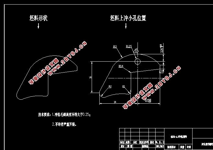
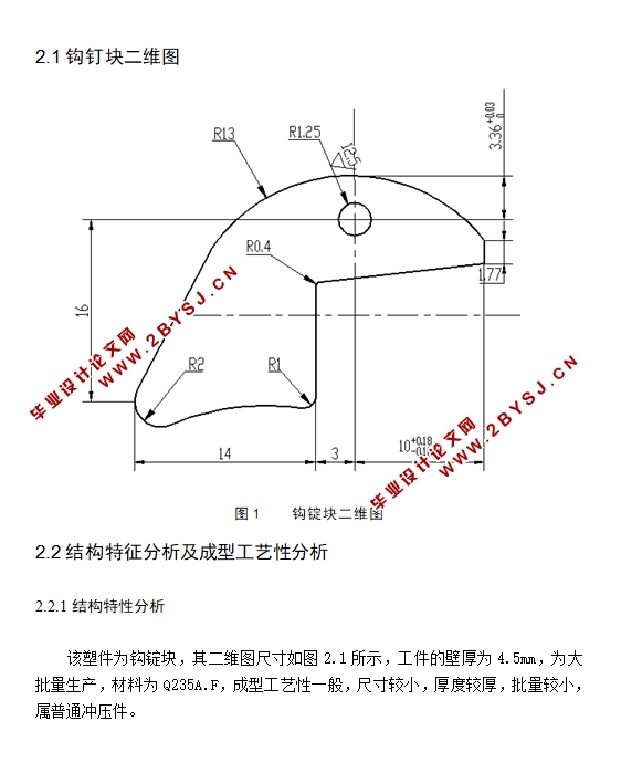
2.1钩钉块二维图 5
2.2结构特征分析及成型工艺性分析 5
2.2.1结构特性分析 5
2.2.2成型工艺性分析 6
2.2.3 冲裁件材料的基本性能 6
3 厚板冲小孔有限元模拟及其相关分析 8
3.1有限元模拟及厚板冲小孔概述 8
3.1.1有限元模拟 8
3.1.2厚板冲裁模拟概述 8
3.1.3金属弹塑性大变形的有限元模拟 9
3.1.4材料断裂准则及断裂模拟 10
3.1.5有限元网格重划分 11
3.2 导入deform前相关准备 11
3.3 冲裁加工模拟的建模 12
3.3.1前处理 13
3.3.2模拟过程线框图 15
3.3.3后处理器 15
3.4 模拟结果及讨论 17
3.5 结论 18
4 模具结构设计 19
4.1计算冲压力 19
4.1.1 冲裁力 19
4.1.2 卸料力及推料力 19
4.1.3 总冲压力 20
4.2冲裁间隙 20
4.3凸凹模工作部分尺寸与公差 20
4.4 冲孔凸模的结构设计 22
4.4.1 冲孔凸模的长度尺寸 22
4.4.2 冲孔凸模工作部分结构如下图 22
4.4.3 冲孔凸模的强度校核 23
4.5 凹模的结构设计 23
4.5.1 凹模板的材料,外形和尺寸 23
4.5.2 凹模板的厚度 23
4.5.3 凹模板上孔壁的最小尺寸 23
4.5.4 凹模工作部分结构图 24
5 冲压成形工艺与设备 25
5.1冲压工艺方案及模具形式的确定 25
5.1.1 工序的确定 25
5.1.2 模具形式的确定 25
5.2 冲压设备的确定 25
5.2.1 规格选用原则 25
5.3 设备及相关模架确定 26
5.3.1 压力机确定及其参数 26
5.3.2 模架相关确定 27
5.4模具整体设计形式 32
6 填写冲压工艺卡和编写技术文件 35
参考文献 37
致 谢 38
