
带料切口连续拉深级进模具设计(空心铆钉制件)
无需注册登录,支付后按照提示操作即可获取该资料.
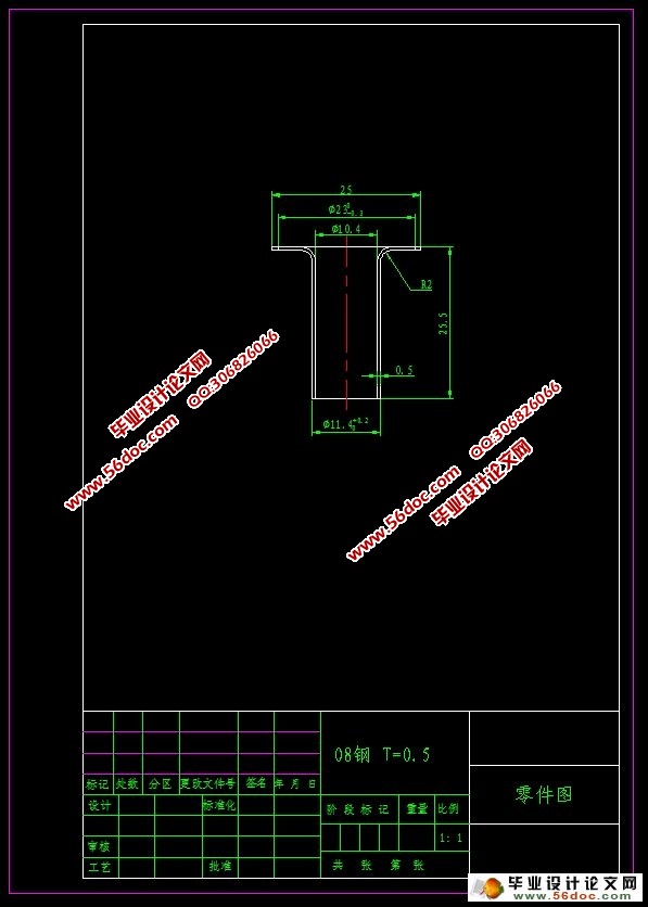
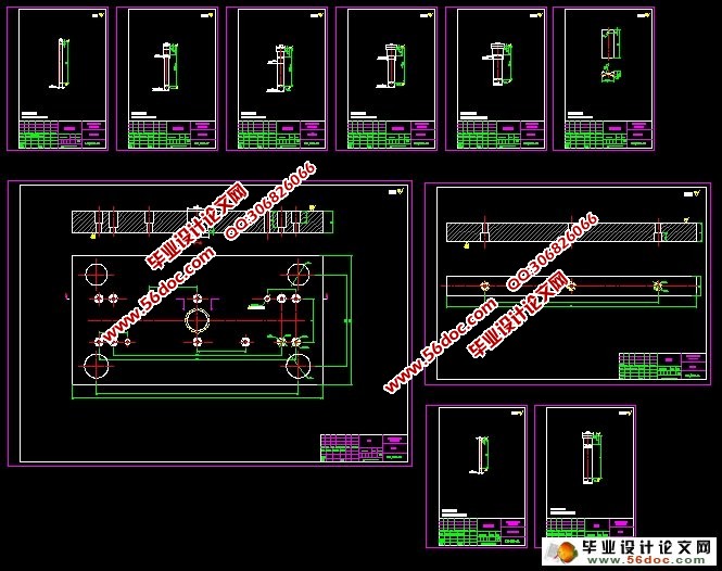
带料切口连续拉深级进模具设计(空心铆钉制件)(任务书,开题报告,中期检查表,论文说明书12000字,CAD图26张)
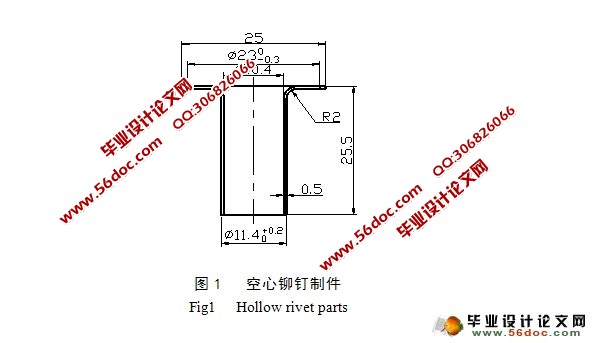
摘 要:带料连续拉深分无工艺切口拉深和有工艺切口拉深,有工艺切口连续拉深就是在首次拉深前,带料上个工序之间切开一个工艺切口,这样当首次和以后各次拉深时,两次工序间的相互影响、相互约束较小,但相对的,耗费的材料较多。
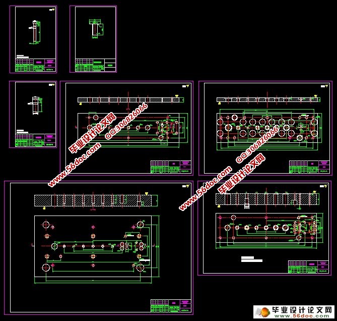
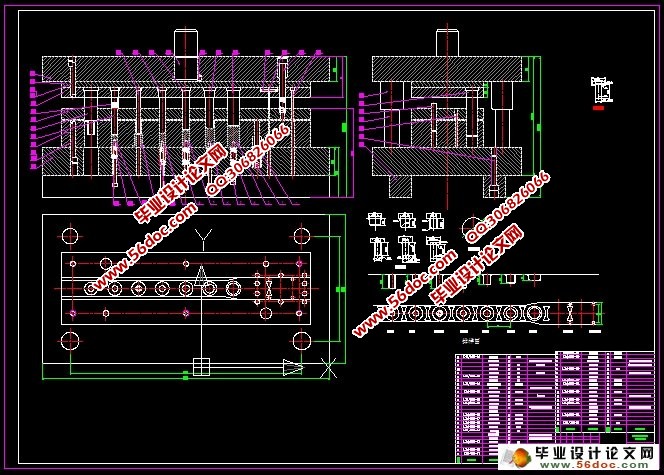
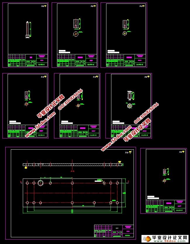
以薄壁宽凸缘筒形件生产为例,设计一例连续模,首先对零件进行工艺分析,有拉深,冲孔,翻边,落料工序,每个工位之间都有尺寸关系,因为是大产量的小型筒形拉深件,一般采用带料连续拉深。采用普通的单工序模或复合模冲制生产的话,需多副模具、多台冲床、多个操作人员才能完成全部工序的冲压制造而且产品质量和生产效率都低。故选多工位级进模具的生产工艺方案,可以提高材料的利用率和模具的使用水平,节省设备。其次经过计算分析确定工艺方案完成该模具的排样设计,凸、凹模工作部分的设计计算,还有模具结构和工艺零件设计。
关键词:工艺性分析,工艺计算,排样,级进模,工艺切口。
Design of Continuous Drawing Progressive Die for Material with Incision
Abstract:Strip continuous deep drawing process of drawing and process without incision incision drawing, process notch continuous drawing is in the first drawing, a strip of material processes a process between incision incision, such that when the first and later the drawing, the two processes of mutual influence, mutual constraint is smaller, but the relative, spend more material.
According to the thin wall Wide-flange cylindrical parts production as an example, a design of progressive die, the first parts of the process analysis, there is deep drawing, punching, flanging, blanking process, each station has the size relations, because it is high yield small cylindrical deep drawing parts, generally use the strip continuous deep drawing. Using the ordinary single-operation die or compound die punching production, need to die, punch, a plurality of operating personnel can complete all processes of stamping manufacturing and product quality and the production efficiency is low. The multi-position progressive die for the production process, can improve the utilization ratio of materials and mold level of use, saving equipment. Secondly, through calculation and analysis to determine the process plan to complete the mold layout design, convex, concave die part of the design calculation, and the die structure and process design.
Key words:Process analysis, Process calculation, Nesting progressive, Die Process incision.
目 录
摘要…………………………………………………………………………………1
关键词…………………………………………………………………………………1
1 前言………………………………………………………………………………2
1.1 冷冲压术的发展趋势……………………………………………………2
1.1.1 冷冲压设备自动化………………………………………………2
1.1.2 提高模具的加工效率……………………………………………3
1.1.3 注重开发大型,精密,复杂模具………………………………3
1.2 模具技术发展的几个特点………………………………………………3
2 工艺性分析………………………………………………………………………4
2.1 冲裁件的结构工艺性……………………………………………………5
2.2 制件冲压工艺方案的确定………………………………………………5
3 制件排样图的设计及材料利用率的计算………………………………………5
3.1 展开尺寸的计算…………………………………………………………5
3.2 拉伸次数的确定…………………………………………………………7
3.3 制件排样图的设计………………………………………………………9
3.3.1 搭边与料宽………………………………………………………10
3.3.2 材料利用率的计算………………………………………………10
4 确定总冲压力和选用压力机及计算压力中心………………………………11
4.1 冲裁力的计算…………………………………………………………11
4.1.1 冲导正孔力计算………………………………………………11
4.1.2 切废料力计算…… …………………………………………11
4.1.3 拉深力计算……………………………………………………11
4.1.4 冲孔力计算……………………………………………………12
4.1.5 翻孔力一般不大………………………………………………12
4.1.6 落料力计算……………………………………………………13
4.1.7 卸料力、推件力及顶件力的计算…………………………13
4.2 压力中心的计算…………………………………………………………13
4.3 压力机的选用……………………………………………………………14
5 凸、凹模刃口尺寸计算…………………………………………………………15
5.1 落料,冲孔凸、凹模刃口尺寸…………………………………………15
5.1.1 计算原则…………………………………………………………15
5.1.2 冲裁间隙对冲裁力的影响………………………………………15
5.1.3 冲裁间隙对斜料力、推件力、顶件力的影响…………………15
5.1.4 冲裁间隙对尺寸精度的影响……………………………………16
5.2 凸模和凹模配合加工……………………………………………………16
5.3 拉深模……………………………………………………………………17
6 模具整体结构形式设计…………………………………………………………19
7 模具零件的结构设计……………………………………………………………21
7.1 拉深凸模的设计…………………………………………………………21
7.1.1 凸模1……………………………………………………………21
7.1.2 凸模2……………………………………………………………21
7.1.3 凸模3……………………………………………………………22
7.1.4 凸模4……………………………………………………………22
7.1.5 凸模5……………………………………………………………23
7.1.6 翻孔凸模…………………………………………………………23
7.2 凹模的设计……………………………………………………………24
8 装配模具………………………………………………………………………24
设计小结……………………………………………………………………………25
参考文献……………………………………………………………………………25
致谢…………………………………………………………………………………26