
桶盖注塑模设计(含CAD零件图和装配图)
无需注册登录,支付后按照提示操作即可获取该资料.
桶盖注塑模设计(含CAD零件图和装配图)(任务书,开题报告,中期检查表,论文说明书15300字,CAD图6张)
摘要
根据复杂外轮廓塑件的结构特点,本模具合适选用直浇口和简单分行面,通过斜滑动型芯、弹簧、活动型芯等抽芯机构的有机组合,使模具结构合理,运行灵活、平稳、可靠。
该塑件是一个内部带侧凹的桶盖 ,以它为例来介绍结构复杂、形状不规则的该塑件的成型工艺和模具设计。采用多种组合的抽芯机构,使塑件一次性成型。即定模抽芯机构和楔柱连杆联合机构共同完成塑件抽芯,活动型芯完成在楔柱连杆联合的驱动下完成桶盖提手部分的抽芯与成型;利用活动滑块完成塑件三处内侧凹的侧向抽芯,保证了制品的成型质量。实践证明组合抽芯机构运行安全可靠,自动化程度高,能满足产品成型要求。
关键词:
塑料模 多种联合抽芯机构 滑动型芯 活动镶件 内侧凹 直浇口 侧抽芯机构
Abstract
According to the structure characteristics of plastic part with complex profile,through proper selection of adirect gate and a simple parting line and reasonable ,combination of the slant sliding core、spring、and movable insert of the core-pulling system,the mould structure was designed reasonblly and safely 。
The plastic part is a bucket lid with the inside slot of the part 。Taking the bucket lid as example , the moulding of the plastic part with complicated structure and irregular shape was introduced 。By adopting the multi-combination core-pulling mechanism,the plastic could be formed by a single moulding 。Practices proved the multi-combination core-pulling mechanism run safe and reliable , and is of hige-level antomation ,could meet the requirement of the products 。
Keywords:
Plastic moulding The multi-combination core-pulling mechanism
Sliding core Movable insert Concaves in the side Direct gate
Slide core-pulling mechanisms
插图清单
图1.1 产品零件图-----------------------------------------------------03
图1.2 制件体积分割图-------------------------------------------------------------------------06
图2.1 分型面布置图----------------------------------------------------------------------------09
图2.2 直浇道设计草图-------------------------------------------------------------------------11
图2.3 直浇道衬套图----------------------------------------------------------------------------12
图2.4 定位环设计图----------------------------------------------------------------------------12
图2.5 抽芯距计算示意图----------------------------------------------------------------------13
图2.6 冷却水道布置图-------------------------------------------------------------------------15
图2.7 脱模力计算示意图----------------------------------------------------------------------16
图2.8 两瓣活动型芯动作示意图-------------------------------------------------------------17
图2.9 导柱结构图-------------------------------------------------------------------------------19
图2.10导套结构图-------------------------------------------------------------------------------19
图2.11限位拉杆设计图-------------------------------------------------------------------------20
表格清单
表3-1 型芯和型腔工作尺寸的计算过程表格----------------------------------------------21
表5-1 型芯的加工工艺过程-------------------------------------------------------------------26
表5-2 动模板的加工工艺过程----------------------------------------------------------------27
目录
绪 论---------------------------------------------------------------------1
任务来源及设计意义---------------------------------------------------3
1 设计任务来源 ------------------------------------------------------------------------3
2 设计目的及意义-----------------------------------------------------------------------3
第1章 模塑工艺规程编制------------------------------------------4
1.1 塑件的工艺性分析---------------------------------------------------------------------4
1.2 塑件体积和质量的计算---------------------------------------------------------------5
1.3 塑件注塑工艺参数的确定------------------------------------------------------------7
第2章 注塑模的结构设计--------------------------------------------8
2.1型腔数目的确定------------------------------------------------8
2.2 制品在模具中的位置的确定-------------------------------------8
2.3 分型面的形式以及位置选择-------------------------------------9
2.4 排气系统设计--------------------------------------------------------------------------10
2.5 浇注系统的设计与计算--------------------------------------------------------------10
2.6 侧抽芯机构设计与计算--------------------------------------------------------------12
2.7 模具加热与冷却系统的设计--------------------------------------------------------14
2.8 脱模机构的设计与计算--------------------------------------------------------------15
2.9 导向定位系统以及其他零件的设计-----------------------------------------------18
2.10 成型零件结构设计------------------------------------------------------------------20
第3章 模具设计的有关计算和注塑机参数校核----------------21
3.1 模具设计的相关计算-----------------------------------------------------------------21
3.2 模具闭合高度的确定-----------------------------------------------------------------23
3.3 注塑机参数校核----------------------------------------------------------------------23
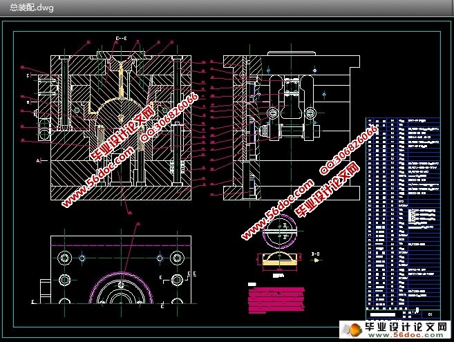
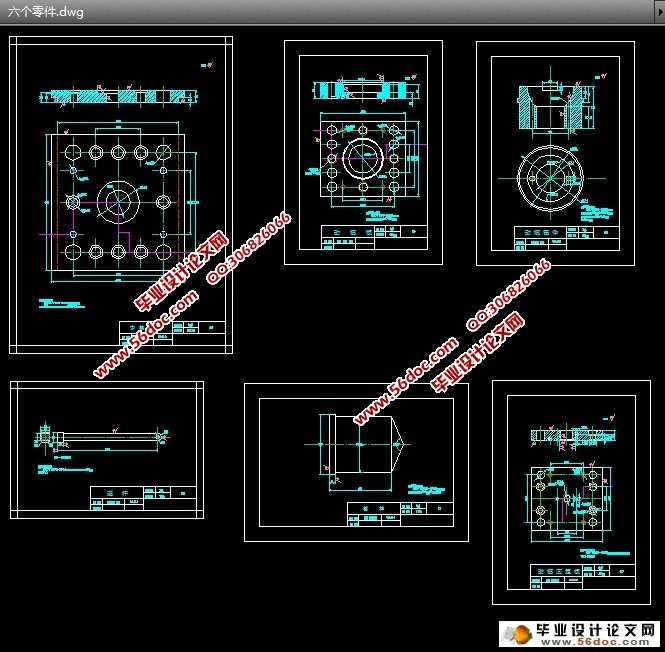
第4章 模具总装图和非标准零件工作图的绘制----------------25
第5章 编写主要零件加工工艺规程-----------------------------26
5.1 主型芯的加工工艺--------------------------------------------------------------------26
5.2 动模板的加工工艺--------------------------------------------------------------------27
第6章 模具的装配和验收-----------------------------------------28
设计总结-----------------------------------------------------------------30
致谢-----------------------------------------------------------------------31
参考文献-----------------------------------------------------------------32