
窗帘遥控器导滑轮注塑模的设计(含CAD零件图装配图)
无需注册登录,支付后按照提示操作即可获取该资料.
窗帘遥控器导滑轮注塑模的设计(含CAD零件图装配图)(开题报告,文献综述,设计说明书11500字,CAD图7张)
Remote control curtain guide pulley injection mold
摘 要
当塑料制件整体为旋转体,需要大批量的生产,且制件的整体尺寸较小,则需要在生产中使用的模具提高生产率,降低其制造成本。因为塑料部件具有凹槽,所以模具采用侧向分型的结构,利用侧向分型机构中的斜导柱,将原本左右开模的动作,变成上下运动。当侧芯型滑块从成型塑件表面的凹槽离开时,利用固定在推板固定板上的推管,使成型的滑轮脱离模具。对于排气,在设计中,分型面选在塑件最大尺寸的位置处,可以利用其之间的空隙排气。对于型腔,选取的是一模两腔,进而增大塑件的产量。对于材料,聚甲醛耐磨性好,选其作为滑轮的材料。
关键词:侧向分型;浇注系统;分型面
Abstract
When the whole shape of the plastic parts of the framework is a rotating body, and the need to mass production. However, the parts of the overall size of the smaller, so in the injection mould used in production to improve productivity, reduce the manufacturing cost. Because of the structure of the plastic part with a groove, so the mold with lateral type, using side parting mechanism in the slanted guide pillar, originally about opening action, become. When the side core type sliding block is left from the groove of the plastic part surface, a push tube is fixed on the fixing plate of the push plate. In the design, the parting surface is chosen to be located at the position of the maximum size of the plastic part, which can be used to exhaust the air between the exhaust gas and the air. For the cavity, the selection of a mold two cavity, and then increase the output of plastic parts. For materials, the good wear resistance of poly formaldehyde, the selection of the material as a pulley.
Key words: lateral type ; casting system; the parting surface
目 录
绪 论 1
1 塑件成型工艺性分析 2
1.1 塑料制件原材料分析 2
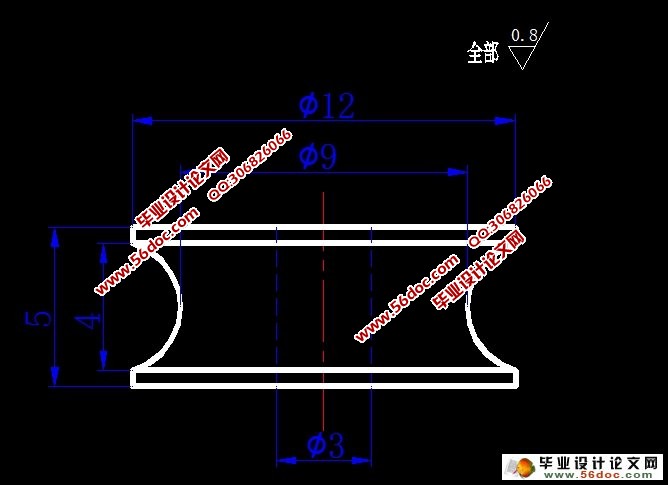
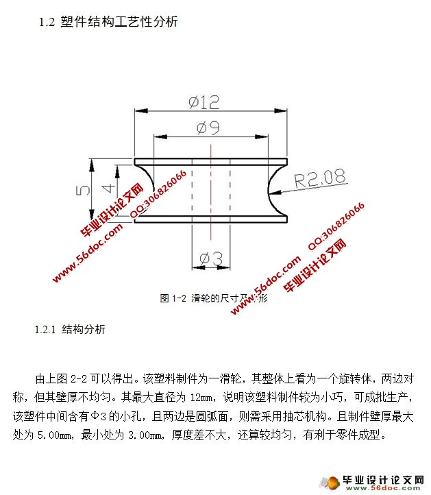
1.2 塑件结构工艺性分析 3
1.2.1 结构分析 3
1.2.2 尺寸精度分析 4
1.2.3 表面质量的分析 4
1.3 注塑模工艺条件及成型过程 4
1.3.1 注塑模工艺条件 4
1.3.2 注射成型过程 4
1.3.3 聚甲醛注射成型工艺参数 5
2 初选注射机及确定模具结构形式 6
2.1 分型面的确定 6
2.1.1 方案一 6
2.1.2 方案二 7
2.2 型腔的排列方式与数量的确定 7
2.2.1 型腔数量 7
2.2.2 型腔的排列形式选择 7
2.2.3 模具结构的初步确定 8
2.3 注射机型号的确定 8
2.3.1 注射量的计算 8
2.3.2 初步计算浇注装置的凝料体积 9
2.3.3 选择注射机 9
2.3.4 校正注射机的相关参数 9
3 浇注系统的设计 10
3.1主浇道的设计 10
3.1.1 主流道的凝料体积 11
3.1.2 主流道当量半径 11
3.1.3主流道浇口套的形式 11
3.2 分流道的设计 12
3.2.1 分流道的布置形式 12
3.2.2 分流道的长度 12
3.2.3 分流道的横截面与其尺寸 12
3.2.4 分流道的表面粗糙度 13
3.3 浇口的设计 13
3.3.1侧浇口尺寸的确定 14
3.4 选择推出方式 14
3.5 复位机构的设计 14
4 成型零件工作尺寸计算 15
4.1 芯腔和型芯的工作尺寸的计算 15
4.2 型腔侧壁厚度和底板厚度的计算 16
4.2.1 型腔侧壁的厚度 16
4.2.2 底板厚度的计算 17
4.3 型芯的结构设计 17
5 侧抽芯机构的设计 18
5.1 斜导柱的设计与计算 18
5.1.1 斜导柱的倾角α 18
5.1.2 斜导柱的结构设计 18
5.1.3 抽芯距的确定 19
5.1.4抽芯力的计算与斜导柱受力计算 19
5.1.5 斜导柱的工作长度 20
5.1.6 斜导柱固定部分的长度 21
5.1.7 斜导柱的总长度 22
5.2 斜滑块(型腔)的设计 23
5.3 楔紧块的设计 23
5.4 滑块的定位装置设计 23
5.5 斜滑块的导滑槽设计 24
6 温度调节系统 24
6.1 模具加热系统的设计 24
6.1.1 电阻加热的形式 25
6.1.2 电阻加热的计算 25
6.2 设计模具的冷却系统 26
7 选择模架与校核 26
7.1各模板尺寸的确定 26
7.2 模架尺寸的校核 27
7.3 模具在注射机上的安装方法 27
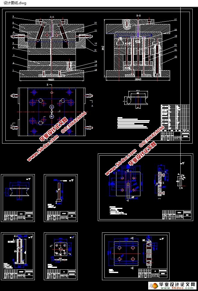
8 模具总装配图 28
结 论 29
致 谢 30
参 考 文 献 31