自行车中轴碗模具设计(含CAD零件图装配图)
无需注册登录,支付后按照提示操作即可获取该资料.
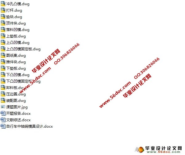
自行车中轴碗模具设计(含CAD零件图装配图)(开题报告,文献综述,设计说明书10800字,CAD图15张)
摘 要
拉深是冲压几个基本工序当中的一个,在模具和压力机的作用下,将平面板料冲制成各种筒形开口零件的加工方法。但是,冲压加工出来的制件精度都是比较低的。一般情况下,拉深件的尺寸精度在IT11-IT13。
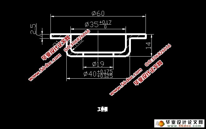
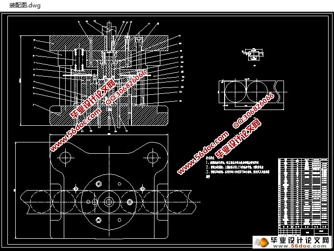
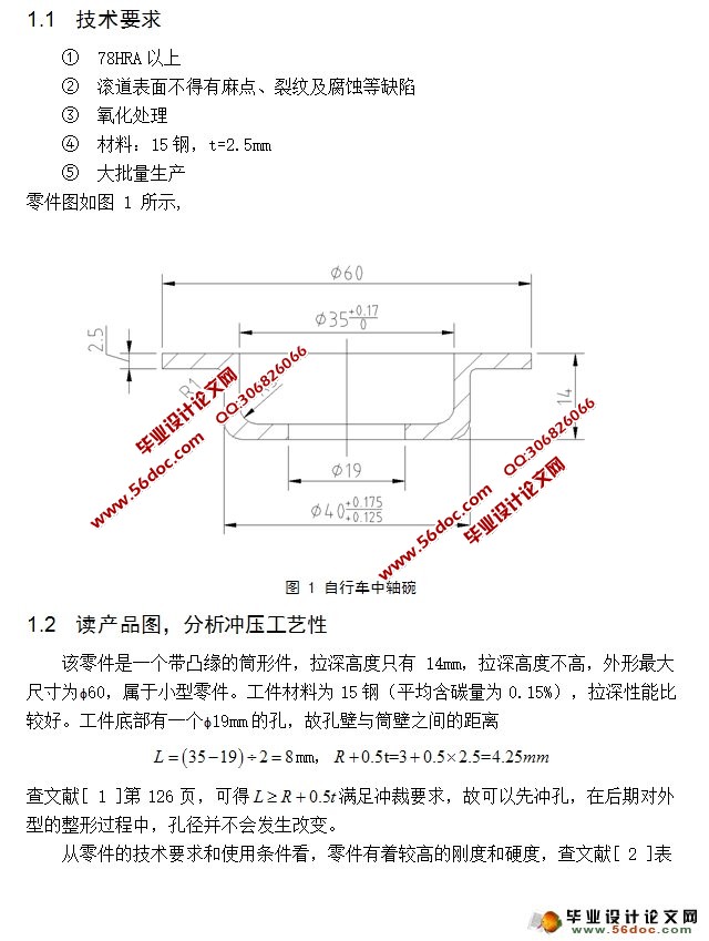
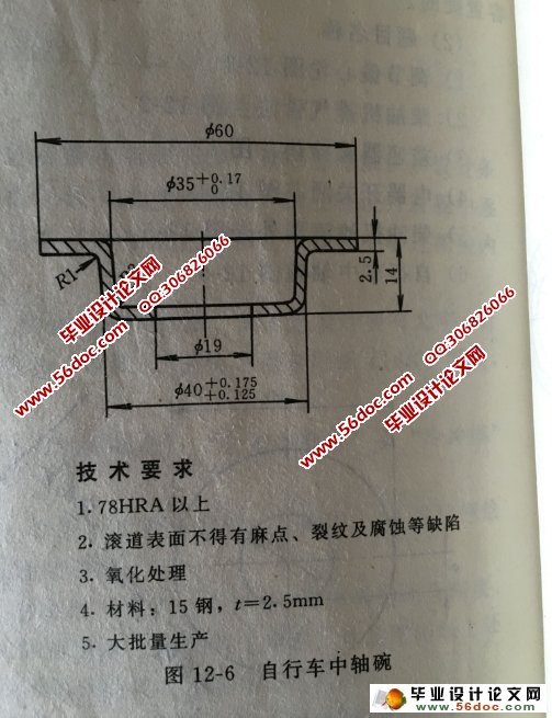
筒形件是非常典型的一个拉深件,我们所用的教材上都是这种简单拉深的模具。对于我所选的课题,经过一些简单的计算确定自行车中轴碗是能够一次性拉深成功,且先冲制零件上的孔,在后期拉深过程中对孔径的大小并不会产生影响。但是由于其中的一个圆角很小(R=1)且拉深外径ɸ40的尺寸精度要求在IT9级,故一次拉深显然达不到零件的要求,故在落料拉深冲孔过后外加一道整形工序,已满足工件图要求的圆角半径和精度。该零件的基本工序可以初步定为落料拉深冲孔复合,切边整形复合。
关键词:拉深模; 旋转体零件; 筒形件
ABSTRACT
Drawing is one of the basic processes of stamping, in the mold and the role of the press, the plane will be made into a variety of sheet metal open parts processing methods. However, stamping out the parts of the accuracy is relatively low. In general, the dimensional accuracy of drawing parts is IT11-IT13.
Cylindrical parts are very typical of a drawing part, we used the material is a simple drawing of the mold. For my choice of subject, through some simple calculations to determine the bicycle axle bowl is capable of drawing a one-time success, and to punch holes in the parts, in the later process of drawing on the pore size did not influence. But due to one of the fillet is very small (r = 1) and drawing diameter of 22 40 dimensional accuracy requirements in it9 grade, so a drawing is clearly not up to the part of the requirements, so in the blanking, drawing, punching and after plus a shaping process has to satisfy the work drawing requirements fillet radius and the accuracy. The basic working procedure of this part can be initially set as blanking drawing punching composite, cutting edge and plastic composite.
Key words: drawing die; rotating body parts; cylindrical parts
目 录
绪 论 1
1. 零件及工艺性分析 2
1.1 技术要求 2
1.2 读产品图,分析冲压工艺性 2
2. 分析计算确定工艺方案 3
2.1 计算毛坯尺寸 3
2.2 判断拉深次数 3
2.3 判断是否要用压边圈 4
2.4 确定工艺方案 4
3. 主要工艺参数的计算 6
3.1 确定排样、裁板方案 6
3.2 拉深凸、凹模圆角半径 7
3.3 计算工艺力 8c
3.3.1 落料力 8
3.3.2 落料卸料力 8
3.3.3 拉深力 9
3.3.4 压边力 9
3.3.5 冲孔力 9
3.3.6 冲孔卸料力 10
3.3.7 推件力 10
3.3.8 顶件力 10
3.3.9 切边力 11
3.4 冲压设备选取 11
4. 编写冲压工艺过程卡 12
5. 模具结构设计 12
5.1 落料凸、凹模尺寸计算 12
5.2 拉深凸、凹模尺寸计算 14
5.3 冲孔凸、凹模尺寸计算 14
5.4 下凸凹模强度、刚度的校核 15
5.4.1 凸凹模强度校核 15
5.4.2 凸凹模刚度校核 16
6. 选用模架、确定闭合高度及总体尺寸 16
7. 计算模具的其他尺寸 17
7.1 冲孔凸模 17
7.2 落料凹模 18
7.3 上凸凹模 19
7.4 上凸凹模固定板 21
7.5 下凸凹模 21
7.6 下凸凹模固定板 22
7.7 压边圈 23
7.8 垫块 24
7.9 垫板 25
7.10 顶料弹簧 27
7.11 卸料弹簧 29
7.12 顶件橡胶 31
7.13 卸料板 32
8. 编制冲压工作零件工艺卡 33
8.1 冲孔凸模的选材、热处理及加工工艺过程 33
8.2 上凸凹模的选材、热处理及加工工艺过程 34
8.3 下凸凹模的选材、热处理及加工工艺过程 35
8.4 落料凹模的选材、热处理及加工工艺过程 35
8.5 卸料板的选材、热处理及加工工艺过程 35
8.6 模座的选材、热处理及加工工艺过程 36
8.7 导柱、导套的选材、热处理及加工工艺过程 36
9. 模具结构图 38
结束语 41
致 谢 42
参考文献 43
