多功能计步器的设计
无需注册登录,支付后按照提示操作即可获取该资料.
多功能计步器的设计(开题报告,外文翻译,论文14000字)
摘要
论文首先介绍了多功能计步器的起源、背景、发展现状和特点,并阐述了系统基本工作原理、主要功能和相关器件选择,包括主控芯片、传感器及显示屏等,然后详细介绍各模块的硬件电路设计,包含主控电路、计步模块、心率模块、温度模块、显示模块和报警模块,其中计步器采用加速度传感器,心率测量采用光电传感器,体温测量使用温度传感器,三者将采集到的信息处理后经过单片机,经程序实现,显示测量值。最后给出系统调试过程和调试结果。
关键字:计步器 传感器 硬件结构 程序设计
The design of Multi-Function Pedometer
Abstract
In the first place, this paper illustrates the derivation, development status and the features of primitive pedometer. Besides, it presents the principle of operation, main functions and the choice of components, which contain main control chip, sensor and screen, etc. Then it refers to the hardware circuit design in detail, which consists of main control circuit, pedometer module, and heart rate module, display module. Pedometer uses acceleration sensor, heart rate test uses photoelectric sensor and temperature measuring uses temperature sensor. Above three then send information to main control chip and display measurements by operating the programs. Finally, it illustrates the procedure of system debugging.
Keyword: pedometer; sensor; hardware structure; programming design


目 录
摘要 I
Abstract II
第一章 绪论 1
1.1论文研究的背景和意义 1
1.1.1概述 1
1.1.2发展现状及特点 1
1.2课题要求及论文主要内容 2
第二章 多功能计步器的设计方案 3
2.1多功能计步器的设计方案 3
2.2器件的选择 4
2.2.1主控芯片的选择 4
2.2.2计步模块中器件的选择 4
2.2.3心率检测中传感器的选择 6
2.2.4 温度传感器的选择 6
2.2.5 显示模块的选择 6
第三章 系统硬件电路设计 7
3.1单片机最小系统设计 7
3.1.1时钟电路 7
3.1.2复位电路 7
3.2液晶显示器模块 8
3.3报警电路 9
3.4按键电路 10
3.5计步模块电路 11
3.5.1计步器传感器信息采集模块 11
3.5.2无线收发模块 12
3.6心率测量模块电路 12
3.6.1传感器部分电路简介 13
3.6.2滤波电路 14
3.6.3放大电路 15
3.6.4整形电路 16
3.7体温测量模块电路 16
3.7.1温度传感器DS18B20性能 16
3.7.2模块和单片机的连接 16
第四章 系统的软件设计 18
4.1总体程序设计 18
4.1.1发射模块程序设计 18
4.1.2接收信息模块程序设计 19
4.2单片机初始化流程设计 21
4.3计步模块程序设计 21
4.4心率模块程序设计 22
4.5体温模块程序设计 23
4.6 LCD显示程序设计 24
第五章 系统的调试 26
5.1问题与解决方案 26
5.2调试结果 26
5.3设计存在的问题 27
结 语 29
参考文献 30
致 谢 32
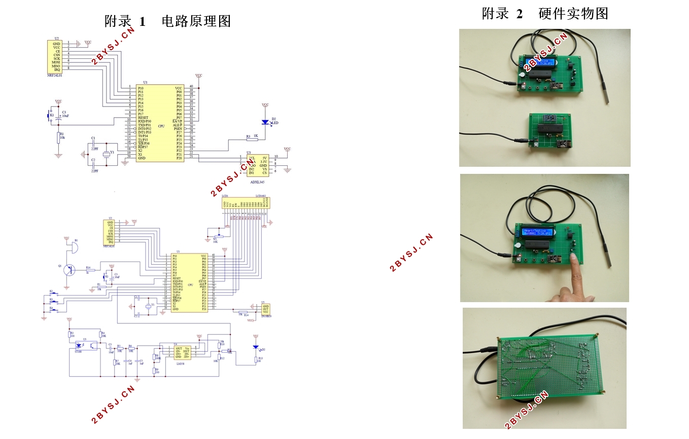
附录 1 电路原理图 33
附录 2 硬件实物图 34
附录 3 源程序 35
